Test Activity
This topic includes information that appears on the Test Configuration tab for all the test cases.
The Test Activity pane defines the type of test that will be performed and the optional features that are unique to the test case.
Use the Test Activity drop-down list to select the functional test you will execute. The list contains the Test Activities that are available for the test case.
Options: available Test Activities
Default: Capacity Test
Use the dropdown list to select Test Activity:
5G Core Emulator
|
Emulation Mode Emulate (AMF) |
5G Core Emulator is a test case that emulates the visited or home network in support of the home routed roaming scenario in 5G system.
Emulation Mode : Use the "Emulate" drop-down box to toggle between the V-Network (visited network) and H-Network (home network). All emulated NFs are optional and can be enabled or disabled with a checkbox. Once selected, the SEPP is forced to be "Initiator" in V-Network and "Responder" in H-Network. The selection of "NRF Interface" is also optional. Once selected, the NRF interface will be enabled for all selected NFs except for the SEPP node and nodes we don't yet have support on NRF. The "Roaming Scenario with SEPP" is currently force selected. All control plane traffic between the V-Network and H-Network must go through the V-SEPP and H-SEPP via the N32 interface. Emulator Options : Currently only enabled for the AMF and SMF node. AMF is available when Emulate = V-Network and AMF is enabled. The content is ported from standalone AMF and SMF node test cases with minor changes. For example, the "N16 Interface" under SMF is force selected in both networks and the "Emulate" is forced to be V-SMF in V-Network and H-SMF in H-Network.
SUT :
Tcl Parameter: Emulate Tcl Parameter: AmfEn
|

AAA Testing
| Protocol (AAA) |
Select RADIUS, Diameter, or Portal as the AAA protocol for the test. The options that are available depend on the test applications licensed for the test system. Options: RADIUS, Diameter, Portal Default: RADIUS
|
|||
| Affinity Mode |
Select Affinity Mode to turn on performance improvement of Diameter Applications. Only available when AAA Protocol = Diameter. Significant performance impact can be achieved with Affinity Mode, especially, when running multiple test cases on the same process. A higher activation rate/throughput can be expected. 5 test cases are optimum as all cores will be used per one process on the C100 S2. Other systems may have a different number of cores per process and the recommended number of test cases should be adjusted accordingly.
|
|||
| Initial Network |
In AAA Server Nodal test case, select Test Activity as Inter-Technology Mobility and select one of the following:
Tcl Parameter: DiaClnInitiateType
|
|||
| Alternate Node |
Use the Alternate Node checkbox to enable the Alternate Node authentication, and the Alternate Node pane on the RADIUS tab is enabled, allowing you to define the NAS emulator. IP Address AllocationIn AAA Server Node testing, select the IP Address Allocation checkbox to define the IP address pools (IP Address Allocation) and methods (Address Pool Selection Method) used to dynamically allocate MN IP addresses from a virtual AAA or DHCP server. The IP Pools tab becomes available when you select this checkbox. Tcl Parameter: NasNode2AuthenticationEnabled |
|||
| Dual Stack |
In AAA Serve Node test case, use Dual Stack to return both IPv4 and IPv6 addresses when requested. Dual Stack is available for your selection only when AAA Protocol = Radius and IP Address Allocation is selected.
Type: True, False Default: False. Tcl Parameter: AaaIpAddrDualStackEn
|
|||
| CoA Simulation |
In AAA Server Node testing, select the CoA Simulation check box to enable and define the CoA Simulation parameters (CoA Simulation) on the RADIUS tab. Tcl Parameter: RadCoaSimulationEn |
|||
| Disconnect Simulation |
In AAA Server Node testing, select the Disconnect Simulation checkbox to define the Deactivation Rate (session/sec) for the Mobile Subscribers. Tcl Parameter: RadDisconnEn |
|||
| Diameter IPSec |
In AAA testing, Diameter IPSec is only available when one NAS Node and one dedicated AAA authentication SUT are involved in the test (AAA Test is Authentication Only). In CSN Nodal test case, IPSec is not allowed for Inter-ASN mobility but it is allowed for Inter-Tech mobility since the Target NAS is not used.
|
AMF Nodal Testing - 5G
| Capacity Test, Session Loading Test, Inter Technology Mobility, Intra-AMF Mobility, Inter-AMF Mobility, Command Mode and Sequencer | Always enabled to perform UE and gNodeB emulation. The following interfaces are always available for testing:
|
||||||||||||||||||||
| Initial Network |
Available when Test Activity = Inter Technology Mobility. Select Initial Network from dropdown list. Options: 5GS , LTE Initial Network indicates where the UE will initially attach / register. Select the Handoff Protocol below to indicate the "Target" network. For example: Initial Network = 5GS , Handoff Protocol = LTE (which is the Target). The UEs will initially attach / register to 5GS then handoff to LTE. The F2 Help key has been enhanced to indicate which network is the Target.
Tcl Parameter : InitiateType |
||||||||||||||||||||
| Handoff Protocol |
Available when Test Activity = Inter Technology Mobility, Command Mode or Sequencer. When Handoff protocol = LTE, the S1-MME becomes available for input. EPS Pane is enabled. When Handoff protocol = WiFi or WiFI-LTE the WiFi Subscribers Pane becomes available for input. Interfaces AP/SSID, SWu IPSec and AAA-RADIUS are enabled. AAA Pane becomes available SUT. Select for VoNR HO <-> Procedure VoWiFi (ePDG) <-> per 23.502 Section 4.11.4. Both Single and Continuous Handoffs from 5GS to WiFi are supported Options : LTE , WiFi, WiFi-LTE Option WiFi-LTE is used to emulate pairs of 5G UE Register to AMF and establish PDU session, setup a VoNR call, handover to WiFi (ePDG as SUT), then handover to LTE (MME as SUT), then end the call and detach 4G. If continuous mobility is configured, UE will do Register again at 5G network in next mobility cycle. AMF and MME SUTs as well as gNB and eNB Control and User nodes become available for input. In AMF Nodal, when "Test Activity" is "Inter Technology Mobility", please enable "Multiple SUTs per gNB" in "Network Devices" >> AMF. Inter technology mobility registration for LTE to 5G supports reallocation: Reference : 23.502 4.11.1.3.3 EPS to 5GS Mobility Registration (Idle) using N26 with AMF Reallocation.
Due to the limitation of SBI configuration, AMF Node can only config multi AMF Nodes when "Inter-AMF Only" or "SMF Emulation" is checked. Options: None, LTE (Command Mode, Sequencer) Tcl Parameter : HandoffProtocol |
||||||||||||||||||||
| Handoff Type |
Available when Test Activity = Inter Technology Mobility, Intra-AMF Mobility, Inter-AMF Mobility and Dual Connectivity. Select Handoff Type from dropdown list. For Mobility Registration from 4G to 5G after EPS fallback, Test Activity = Inter Technology Mobility, Handoff Protocol = LTE, Handoff Type = REG/TAU, enable Continuous Handoff and Initial Network = Target. For 5GS to EPS TAU Scenario see 23.502 Section 4.11.1.3.2. For Mobility Registration Update see 3GPP TS 23.502 Section 4.2.2.2. For RAN Initiated QoS Flow Mobility (per 23.502 section 4.14.1): This procedure is used to transfer QoS Flows to and from Secondary RAN Node. During this procedure, the SMF and UPF are never re-allocated. The UPF referred in this Figure 4.14.1-1 is the UPF which terminates N3 interface in the 5GC. The presence of IP connectivity between the UPF and the Master RAN node, as well as between the UPF and the Secondary RAN node is assumed. If QoS Flows for multiple PDU Sessions need to be transferred to or from Secondary RAN Node, the procedure shown in the Figure 4.14.1-1 below is repeated for each PDU Session.
Options: Handover , REG/TAU (Inter Technology Mobility) Options: Xn , N2, Mobility Registration Update (Intra-AMF Mobility) Options: N2, Mobility Registration Update (Inter-AMF Mobility) Options: RAN Initiated QoS Flow Mobility (Dual Connectivity) Tcl Parameter : HandoffType |
||||||||||||||||||||
| Data Traffic | Enables the L3-7 Interface - Data Traffic tab. | ||||||||||||||||||||
| Data IPSec |
Select to use IPSec to encrypt Data Traffic (L3-7 Interface). Define IPSec parameters on the Data IPSec tab. |
||||||||||||||||||||
| UE-Requested PDU Session Modification |
Select to trigger PDU Session Modification request from UE. Available when NAS-5G SM | NAS 5G Version (24.501) is = > 15.2.0 and when NAS-5G SM | NGAP Version (38.413) is = > 15.2.0. NAS-5G SM | QoS Flow Modification becomes available for input. Available on AMF Nodal, AMF Node and SMF Node test cases. Tcl Parameter: UeReqPduSessionModEn |
||||||||||||||||||||
| PDU Session Secondary Authentication |
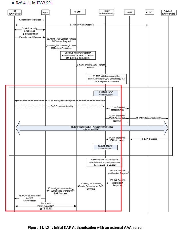
Select for Secondary Authentication during PDU Session Establishment. Available when NAS-5G SM | NAS 5G Version (24.501) is = > 15.2.0 in AMF Nodal / AMF Node and SMF Nodal / SMF Node test cases. Not available when Registration Only is enabled. Max DNN Mode via TDF is not available with this feature. When enabled, the “Number of PDUs” in Test Configuration/Mobile Subscribers panel should be equal to “Number of Data Network Names") in NAS-5G/SM Tab. Enable Include SM PDU DN Req Container in PDU Session Est Req in NAS-5G/SM Tab, Secondary Authentication, EAP Settings (TLS Only) in AMF Nodal and the Secondary Authentication Configuration Timers (Reauthentication Delay (s), T3590 (s)) in AMF Node / SMF Node. This options is not available in SMF Nodal when UPF Node Emulation is enabled. The following use cases are supported by AMF Nodal 1) PDU Session Secondary Authentication during PDU Session Establishment procedure 2) Re-authentication after PDU Session Establishment procedure 3) PDU Session Establishment Reject by NW 4) PDU Session Release by NW Supported Call Flows:
In B2B test for AMF Nodal, AAA Node Test Case for DN-AAA is not used because AMF currently does not support the interface to communicate with DN-AAA however, SMF Node does support it. References: 3GPP TS 23.501: System Architecture for the 5G System; Stage 2 Note: The latest Wireshark doesn't decode IEs in NAS 5G messages and http2 frame headers of NamfCommunication_N1N2MessageTransferReq when messages include EAP message IE/SM PDU DN request container container IE. Tcl Parameter: PduSessionSecAuthEn |
||||||||||||||||||||
| Registration Only | Select for Registration Only. Registration procedure per reference: 3GPP TS 23.502, Figure 4.2.2.2.2-1
Currently session loading supports registration followed by pdu establishment request with follow-on request pending bit set to 1. Thus feature will send registration request message not followed by pdu establishment and follow-on request pending bit set to 0. Thus, the activity becomes (Reg/periodic reg/./DeReg, PDU session establishment is not triggered)
Table 9.11.3.7.1: 5GS registration type information element
When Registration Only is checked, the Number of PDUs is forced to 0 and UE-Requested PDU Session Modification, Data Traffic, External Data, Data IPSec, Vo5G, and SMF/UPF Node Emulation are disabled. Also, the NAS-5G|SM and N3 tabs are hidden. Enable or Disable the NAS-5G|MM, Initial Registration with Follow On to set the Follow-on request bit. Not available when Test Activity = Command Mode, Sequencer or Inter Technology Mobility Tcl Parameter: RegistrationOnlyEn |
||||||||||||||||||||
|
N2 IPSec / Target N2 IPSec
|
Select for N2 IPSec - Additional details here - N2 IPSec | ||||||||||||||||||||
| N3 IPSec / Target N3 IPSec | Select for N3 IPSec - Additional details here - N3 IPSec | ||||||||||||||||||||
| N4 IPSec | Select for N4 IPSec - Additional details here - N4 IPSec | ||||||||||||||||||||
| Vo5G | Select for SIP Vo5G. | ||||||||||||||||||||
| EPS Fallback |
Available when Test Activity = Inter Technology Mobility with LTE and Vo5G is enabled and Test Activity = Command Mode / Sequencer with Handoff Protocol = WiFi-LTE and Vo5G. Select to emulate the scenario that a Vo5G call is attempted while the gNB does not support Vo5G and has to fallback to an eNB to start the media traffic. The fallback itself is triggered by receiving of a PDU Session Resource Modify Request message on the Vo5G PDU. The gNB that's unable to support Vo5G will send back a response with reject cause ims-voice-eps-fallback-or-rat-fallback-triggered and initiate inter-tech mobility to LTE. After the UE is successfully handed over to LTE, the network will resume the call attempt by initiating a Create Bearer Request / Activate Dedicated EPS Bearer Context Request to create the media bearer. Mobility between 5GS and EPS without N26 is not yet supported. Tcl Parameter: EpsFallbackEn |
||||||||||||||||||||
| Fireball | Select for Fireball testing. Requires Capacity test and Data Traffic enabled but not Data IPSec or N3IWF. | ||||||||||||||||||||
| SMSo5G | Select for Short Message Service over 5G. | ||||||||||||||||||||
| N3IWF |
Enable N3IWF ( Non-3GPP InterWorking Function). Per 3GPP 23.502 . The NWu interface becomes available for input with TCP and NWu IPSec tabs. Available when Test Activity = Capacity Test or Session Loading Test or Inter Technology with Handoff Protocol = WiFi (Support for Handover of a PDU session procedure between 3GPP and Untrusted non-3GPP access) or LTE ( Handover procedures between EPS and 5GC-N3IWF and back based on Spec 3GPP 23.502 Section 4.11.3). Support handover a UE from a source Untrusted non-3GPP access to a target 3GPP access and UE handover a PDU Session from Untrusted non-3GPP access to 3GPP access based on 3GPP 23.502 Section 4.9.2 ) Note : SMF and PGW-C should be tightly coupled in the same test case to exchange bearer context during mobility between 5GC-N3IWF and EPS (3GPP 23.502 Sec-4.11.3.2). AMF Node test case with SMF Emulation and PGW-C Emulation is recommended. Do not use the MME Node test case for PGW Emulation for this mobility scenario. Tcl Parameter: N3iwfEn |
||||||||||||||||||||
| TWIF |
Select for the TWIF - Trusted WLAN Interworking function. When enabled, the AAA Interface (RADIUS ), AP/SSID, GRE become available for input. AAA SUT Pane becomes available as well as the AP WAN Node. Currently we only support Number of PDUs set to 1. Limitations : TWIF is only allowed with these options: Data Traffic , Data IPSec, External Data, Vo5G Initial Phase 20.2.0 release supports ; 1 UE, 1 Node, No PDU no Data Phase 2 in 20.4.0 release includes :
Spec Reference:
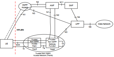
The following use cases are supported by AMF Nodal: Untrusted & Trusted 3GPP Access – TNGF
For Devices without 5G NAS over WLAN Access (TWIF)
1. UE initiates EAP procedure to send AAA requests to TNGF. EAP message will be encapsulated into AAA message. The AAA request also includes the TNAP identifier, which can be treated as the User Location Information. The TNAP Identifier shall include the SSID of the access point to which the UE is attached. The TNAP Identifier shall include at least one of the following elements unless otherwise determined by the TWAN operator's policies: - the BSSID (see IEEE Std 802.11-2012 [106]); - civic address information of the TNAP to which the UE is attached. Per TS 29.571 V16.5.0 section 5.4.4.62Type: TnapId :Table 5.4.4.62-1: Definition of type TnapId
2). During EAP-5G procedure TNGF key is created in the UE and in the AMF after the successful authentication. The TNGF key is transferred from the AMF to TNGF in step 10a (within the N2 Initial Context Setup Request). The TNGF derives a TNAP key, which is provided to the TNAP. 3). After receiving the TNGF key from AMF in step 10a, the TNGF shall send to UE an EAP-Request/5G-Notification packet containing the "TNGF Contact Info", which includes the IP address of TNGF. Phase 2 (release 20.4) adds support for the section circled below:
Tcl Parameter: TwifEn |
||||||||||||||||||||
| 5G-RG |
Available in AMF Nodal test case for Capacity or Session Loading test activities. Disabled by any test options other than Data Traffic, Data IPSec, External Data, and Vo5G. Select for 5G-RG Emulation support in AMF Nodal. The System Under Test (SUT) is AGF with Landslide simulating 5G-RGs, AN & PDN as shown in the figure below. Landslide will generate control and user plane test traffic and initiate various procedures towards the AGF & UPF.
PPPoE procedures
Spec Reference:
When enabled, the PPP Tab becomes available for input. The SUT is AGF. In release 23.3, the following changes were made : In the Network Devices, "AP-WAN Node" tab was renamed to "5G-RG Node" tab without "# of Nodes". The "Starting IP address" was removed as what is selected for 5G-RG is the Eth Port, not an IP address. The 5G-RG tab in Mobile Subscribers has been removed, and the MAC Address field was moved to the "5G-RG Node" tab on Network Devices. The UE IP address is derived from the NAS-5G/SM PDU IPv6 Address Pool, not from UE Static IPv4. Tcl Parameter: 5gRgEn |
||||||||||||||||||||
|
Reset UE Positioning Stored Info |
LCS Support is now available in the 5G AMF Nodal / gNB CU SA Nodal and AMF Node test cases. Currently, we support UE Based and UE assisted A-GNSS method. If TDF file is used, only the A-GNSS related parameters need to be configured.
If Reset UE Positioning Stored Info is enabled (Per TS38.509 6.6.1), “NRPPa” command is triggered with the following messages;
Protocol discriminator: 1111 Skip indicator: 0000 = No indication of selected PLMN (0) Message type: Reset UE Positioning Stored Information (0x88) UE Position Technology: 0000 0000 = AGNSS (0)
If Reset UE Positioning Stored Info is disabled, “NRPPa” command is triggered with the following message;
|
||||||||||||||||||||
| Emergency Alert |
Select for the 5G Wireless Emergency Alert broadcast. Commercial Mobile Alert System (CMAS) Broadcast System for 5G. In AMF Node/Nodal test cases and gNB CUSA Nodal TC, the PWS Tab for N2 interface allows the user to define requests related to Commercial Mobile Alert System (CMAS) Broadcast System for 5G. Per 3GPP 23.401. Call flow:
Tcl Parameter: AmfEmergencyAlert Tcl Parameter: GnbEmergencyAlert |
||||||||||||||||||||
| Enable E911 Call |
Available on AMF Nodal test for Capacity or Session Loading test activities, Vo5G is enabled, Number of PDUs > 1 , NAS 5G Sm - Number of Network Names > 1, and at least 1 DNN must have the Emergency option selected. Select to emulate real 5G UE’s E911 call flow that is consisting of the following steps:
When enabled, the E911 Vo5G tab is for the Emergency PDU and a second Gm2 for the Emergency Profile - Control: SIP , Control - TCP Separate SIP Call Flow profile per Normal and Emergency PDU provides flexibility in configuring context of SIP messages over mechanism of SIP Configurable via that two Gm Tabs (Gm and Gm2) have to be exposed in GUI level. Gm Tab/Profile is the default one, and it is associated with Vo5G Tab/Profile while Gm2 Tab/Profile is bound to E911 Vo5G. Example : The E911 Call mechanism uses the highlighted timers (Start PDU Delay (After Registered) (ms), Start PDU Delay (After Prev-PDU) (ms)) as shown in screenshot below:
In the case of two Vo5G PDNs only, ims and sos:
In the case of 3 PDUs, data, ims and sos:
Two Vo5G Profiles, Normal and Emergency, can be implemented by means of exposure of two Vo5G Tabs :
Tcl Parameter: E911CallEn |
||||||||||||||||||||
| SMF/UPF Node Emulation |
Select for SMF/UPF Node Emulation. For SMF / UPF Emulation, the Nsmf, SMF-AMF, N4 (PFCP ) and N6 (N6 Data Traffic) interfaces become available. The SUT is AMF SBI, SMF SBI Node , SMF N4 Node , SMF N4 GTP Node, UPF N3 Node, ,UPF N4 Node and UPF N4 GTP Node. The NAS-5G SM interface has two panels, UE (same as AMF nodal test case) and SMF (same as AMF Node test case). There will be two SM measurements, one labeled SM-UE and the other SM-SMF. The N4 (PFCP ) interface has two panels, UPF (same as UPF Node test case) and SMF (same as SMF Node test case). Tcl Parameter: SmfUpfNodeEmulationEn |
||||||||||||||||||||
| NRF Interface | Available when SMF/UPF Node emulation is enabled. Select to enable the Nnrf Client Interface. NF Tab (NF Consumer - Nnrf Client). NF Tab (NF Producer Nsmf). NRF SBI SUT becomes available for input. NRF Interface is also available on several of the 5G test cases including : Service Based Node, Service Based Node , SMF Node, etc Tcl Parameter: NrfIntfEn | ||||||||||||||||||||
| Support ATSSS |
Select for support for Access Traffic Switching and Steering. Available on AMF Nodal when Test Activity is Inter-Technology Mobility with Wifi Handoff Protocol and N3IWF is enabled and NAS-5G Version 16.5.0 or higher. Support Access Traffic Switching: The procedure that moves all traffic of an ongoing data flow from one access network to another access network in a way that maintains the continuity of the data flow. Access traffic switching is applicable when Home-routed Roaming (UE registered to the same PLMN). Support Access Traffic Steering: The procedure that selects an access network for a new data flow and transfers the traffic of this data flow over the selected access network. Access traffic steering is applicable between one 3GPP access and one Based on 5.32.6 of 3GPP TS 23.501 and 3GPP TS 24.193 Limitations:
Tcl Parameter: AtsssEn |
||||||||||||||||||||
| Support Roaming |
Support Roaming is available on AMF Nodal Test Configuration and AMF Node Emulator Configuration. Available on AMF Nodal when Test Activity is Capacity, Session Loading Test, or Command Mode/Sequencer and Handoff Protocol is “None” or Inter Technology Mobility with Handoff Protocol = LTE and Handoff Type = Handover or REG/TAU and "NAS-5G Version" in Nas 5G Mm is 15.1.0 or higher and "NGAP Version" in N2/NGAP is 15.1.0 or higher. It is disabled when “SMF/UPF Node Emulation”, “N3IWF”, “TWIF”, “5G-RG”, “Support URLLC” and “Support ATSSS” in Test options are enabled. Available on AMF Node when "NAS-5G Version" in Nas 5G Mm is 15.1.0 or higher and "NGAP Version" in N2/NGAP is 15.1.0 or higher. It is disabled when SMF Emulation, UPF Emulation, N22 Interface, N14 Interface are enabled. In AMF Nodal TC, select Support Roaming to indicate whether to include the mapped Home S-NSSAI in NSSAI sent to AMF if available in Requested NSSAI in Registration Request and in Pdu Session Establishment Request. In the case of Requested NSSAI of Registration Request, if the “Mapped Home S-NSSAIs” in “Requested NSSAI” in NAS-5G/MM Tab are configured, it will be included. In the case of Pdu Session Establishment Request, if the “Mapped Home S-NSSAIs” in “Allowed NSSAI” sent by SUT-AMF are available and one of them is matched with S-NSSAI of the PDU session that UE will establish, it will be included. In addition, If “Network Slicing Info” in DNN Tab which the PDU to be established belongs to is configured and its S-NSSAI is one of the Allowed NSSAI in Registration Accept received from AMF and that S-NSSAI has the mapped Home S-NSSAI, UE will include the mapped Home S-NSSAI in NSSAI which is optionally sent together with PDU Session Establishment Request Message. In AMF Node TC, select Support Roaming to indicate whether to support Roaming Scenario for PDU Session Establishment. Whens enabled, AMF will trigger only the Home Routed Roaming scenario when it handles PDU Establishment Procedure, and the SNSSAI for PDU Session has the mapped Home SNSSAI. Select HomeRouted, currently the only option. When Configured NSSAIs is configured in the NAS-5g, AMF Nodal will include Allowed NSSAI with the mapped S-NSSAI in RegistrationAccept message during registration procedure.
Tcl Parameter: SupportRoamingEn Tcl Parameter: PduEstRoamingType |
||||||||||||||||||||
| 5G-GRE |
Select to add Soft GRE feature under User traffic session. Available in AMF Nodal for Capacity or Session Loading Test. It becomes disabled when any other checkbox is enabled except for Data Traffic and Fireball. On the AP/SSID tab for AMF Nodal only, the "Inner VLAN Tag" is allowed for Fireball but "VLAN Tag Type" is restricted to "0x8100".
Interface : AP/SSID ,DHCP and GRE become available for input. The 5G-GRE Pane becomes available for input. L3 measurements are generated when UE DHCPv4 or UE DHCPv6 is enabled for 5G-GRE even when data traffic is not enabled. Enter the number of GRE Subscribers Per PDU in the 5G-GRE Pane. Range : 1 to 100, Default : 1 Select Apply Test Data File to Mobile Subscribers to add UE MAC Address via Test Data File (TDF). Tcl Parameter: 5gGreEn Tcl Parameter: GreSubsPerPdu |
||||||||||||||||||||
| Support NTN |
Select to support NRNTN (Non-Terrestrial Network) network. AMF to send Forbidden TAI(s) to UE during initial Registration, mobility and periodic update Registration, and Service Request procedures. Per 3gpp spec 23.502 release 17.6 sections 4.2.2.2.2, 4.2.3.2. Can be enabled when NAS-5G version is 17.12.0/Sep2023 or higher and NGAP version (N2 tab) is 17.6.0/Sep2023 or higher. Test Activity excludes “Inter Technology Mobility” and “Dual Connectivity”. For AMF Nodal TC , select the NTN Type in the gNB Control Node. For AMF Node TC, enter the Number of Forbidden TACs in the Nas 5G MM Tab. Available on both AMF Nodal / Node test cases. Tcl Parameter: SupportNtnEn |
||||||||||||||||||||
| EPS | Available when Test Activity = Inter Technology Mobility and Handoff Protocol = LTE.
|


AMF Node Testing - 5G
| SMF Emulation | Select to enable to perform AMF (and SMF) emulation. The following interfaces become available for testing:
The SUT is UPF (AMF Node , SMF N4 Node , SMF N4 GTP Node ) When SMF Emulation is enabled, N14 Interface and Intra-AMF Only are not available.
When SMF Emulation is disabled, N11 Interface toward SMF becomes available for testing. Namf, AMF-SMF as well as NAS-5G- MM tab only and N2 - NGAP are available for input. The SUT is SMF SBI SUT (AMF Node and AMF SBI Node)
Tcl Parameter: SmfEmulationEn |
| UPF Emulation |
UPF Node Emulation is available on AMF Node test case. The N4 (PFCP ) and N6 (N6 Data Traffic) interfaces become available as well as UPF N3 Node, ,UPF N4 Node and UPF N4 GTP Node. SMF SBI SUT becomes available for input.
When only "UPF Emulation" is selected and "User Initiates Association" is selected under N4 (PFCP ), Uner the Network Devices/System Under Test section, the "SMF N4 SUT” tab becomes available for input. When both "SMF Emulation" and "UPF Emulation" are selected :
|
| PGW-C Emulation |
Select for PGW-C Emulation. The S2a/S2b/S5/S8 (GTPv2) interface becomes available for input. Enter the EPS Dedicated Bearers per Default. Available on AMF and SMF Node test cases and on gNB CU SA Nodal test case. Tcl Parameter: PgwCEmulationEn |
| N26 Interface | The N26 interface provides a reference point between Access and Mobility Management function (AMF) and the Mobility Management Entity function (MME). The N26 (GTPv2) interface becomes available for input. Available on AMF Node , gNB CU SA Nodal and MME Node test cases (The S11/N26 (GTPv2) interface becomes available for input on MME Node test case). Tcl Parameter: N26En |
| SMSo5G | Select for Short Message Service over 5G. |
| UE-Requested PDU Session Modification |
Select to trigger PDU Session Modification request from UE. NAS-5G SM | QoS Flow Modification is disabled for input. Available on AMF Nodal, AMF Node and SMF Node test cases. |
| NRF Interface |
Select to enable the Nnrf Client Interface. NF Tab (NF Consumer - Nnrf Client). NF Tab (NF Producer - Namf ). NRF SBI SUT becomes available for input. Additional details in this NRF Interface section. |
| N14 Interface |
Available when SMF Emulation and Intra-AMF Only are disabled on AMF Node test case. N14 interface provides a reference point between 2 Access and Mobility Management functions (AMF). Interface AMF-AMF becomes available for input. The SUT is AMF SBI SUT and SMF SBI SUT (AMF Node and AMF SBI Node). The number of AMF Nodes and SMF SBI SUTs are always set to 1. When SMF Emulation is disabled, N11 Interface toward SMF becomes available for testing. Namf, AMF-SMF as well as NAS-5G- MM tab only and N2 - NGAP are available for input. Tcl Parameter: N14En |
| Intra-AMF Only |
Available when SMF Emulation and N14 Interface are disabled on AMF Node test case. The SUT is SMF SBI SUT (AMF Node and AMF SBI Node). When SMF Emulation is disabled, N11 Interface toward SMF becomes available for testing. Namf, AMF-SMF as well as NAS-5G- MM tab only and N2 - NGAP are available for input. SMF SBI SUTs are always set to 1. Tcl Parameter: IntraAmfOnlyEn |
| NLs Interface |
NLs interface provides a reference point between the Access and Mobility Management functions (AMF) and the (LMF) Location Management function. Interface AMF-LMF becomes available for input. The NLs Interface is disabled in test configurations when the AMF SBI Node is not enabled on Network Devices. The AMF SBI Node is enabled when SMF Emulation is off, or any of the following test options are on: Not available when LCS Support is enabled on AMF Node test case. The SUT is LMF SBI SUT. Tcl Parameter: NlsEn |
| NLg Interface |
NLg interface provides a reference point between the Access and Mobility Management functions (AMF) and the (GMLC) Gateway Mobile Location Centre. Interface AMF-GMLC becomes available for input. The SUT is GMLC SBI SUT. The NLg Interface is disabled in test configurations when the AMF SBI Node is not enabled on Network Devices. The AMF SBI Node is enabled when SMF Emulation is off, or any of the following test options are on: Tcl Parameter: NlgEn |
| N12 Interface |
The N12 interface is also enabled on AMF Node Emulator Configuration. The SUT is AUSF SBI. Interface Namf (NF Tab - NF Producer) and AMF-AUSF (NF Tab - NF Consumer) become available for input. AMF SBI Node is available for input. The N12 interface is also available on Service Based Nodal test case. |
| N20 Interface |
The SUT is SMSF SBI, select From AMF - Access and Mobility Function. Interface Namf (NF Tab - NF Producer) and AMF-SMSF (NF Tab - NF Consumer) become available for input. AMF SBI Node is available for input. Tcl Parameter: N20En The N20 interface is also available on Service Based Nodal test case. |
| N22 Interface |
The N22 interface is also enabled on AMF Node Emulator Configuration. The SUT is NSSF SBI. Interface Namf (NF Tab - NF Producer) and AMF-NSSF (Amf to Nssf NF Tab - NF Consumer) become available for input. AMF SBI Node is available for input. The N22 interface is also available on Service Based Nodal test case. Tcl Parameter: N22En
|
| Support URLLC |
Support URLLC is available on AMF Node Emulator Configuration with SMF Emulation enabled and on SMF Node Emulator Configuration and on AMF Nodal Test Configuration. The URLLC (Ultra-Reliable Low Latency Communications) feature comes with two parts, i.e., the control and user plane layer. This feature is specific to the signaling part of redundancy for URLLC in the UE requested PDU Session Establishment procedure. Redundancy is achieved by having two GTP tunnel for the same PDU and the resources have needs to be allocated for the same. URLLC needs a always-on PDU session to be established before hand, this is initiated by the UE and then acknowledged by the network if certain conditions are met and with the local policies. Once the always-on PDU is established, which itself is one of the conditions for Redundancy, other checks have to be verified → SST is 2, 5QI should be set to 82. During or after a URLLC QoS flow establishment, if the SMF decided that redundant transmission shall be performed based on authorized 5QI, NG-RAN node capability and/or operator configuration, the SMF informs the PSA UPF and NG-RAN to perform redundant transmission via N4 interface and N2 information accordingly. 1. Activate Redundant Transmission during PDU Session Establishment procedure. 2. Activate Redundant Transmission during PDU Session Modification procedure per reference is 23.502 and TR 23.725 Limitations : The Redundant TNL information from the UE→SMF is covered, SMF→UPF is not supported. The 5QI value used for URLLC is 82. The Redundant GTP tunnel info: Transport Layer address and gTP-TEID is same as the existing tunnel info. On AMF Nodal test case :
Tcl Parameter: SupportUrllcEn |
| N50 Interface |
The N50 interface is also enabled on AMF Node Emulator Configuration. Interface Namf (NF Tab - NF Producer) becomes available for input. AMF SBI Node is available for input. N50 Interface and Emergency Alert are mutually exclusive. N50 provides a reference point between Cell Broadcast Center Function (CBCF) and the Access and Mobility Management function (AMF). AMF forwarding logic for CMAS warning messages has been added based on 3GPP Spec in section 9.1.3.5.2 of 23.041: The AMF forwards Write-Replace Warning Message Request NG-RAN to NG-RAN nodes. The AMF shall use the list of NG-RAN TAIs to determine the NG-RAN nodes in the delivery area. If the list of NG-RAN TAIs is not included and no Global RAN Node ID has been received from the CBCF, the message is forwarded to all NG-RAN nodes that are connected to the AMF. If a Global RAN Node ID has been received from the CBCF, the AMF shall forward the message only to the NG-RAN nodeindicated by the Global RAN Node ID IE. Ngap Tab (PWS Configuration). Tcl Parameter: N50En |
| N8 Interface |
The UDM (N8) interface is enabled on AMF Node Emulator Configuration. The SUT is UDM SBI. Interfaces AMF-UDM (NF Tab - NF Consumer) and Namf (NF Tab - NF Producer) become available for input. AMF SBI Node is available for input. The N8 interface is also available on Service Based Nodal test case. |
| N15 Interface |
The SUT is PCF SBI, select From AMF (N15)- Access and Mobility Function. Interface Namf (NF Tab - NF Producer) and AMF-PCF (Amf to Pcf NF Tab - NF Consumer) become available for input. AMF SBI Node is available for input. Also available on Service Based Nodal test case when Test PCF (Npcf) and From AMF (N15) are enabled. We have support of UE Policy Association Establishment in SBI Nodal and Node. Now this support has been extended to the N1/N2 interface and all the way to the UE. Per Spec reference is 29.513 sec 5.6.1.2. See figure 5.6.1.2-1 : UE Policy Association Establishment procedure - Non-roaming. 24.501 Annex D defines several UE Policy Delivery Service messages:
They are embedded either in a NAS container on N1 interface or in a Npcf/Namf message. More specifically:
Limitation: For now we only support UE Policy Association Establishment with initial UE registration. |
| N2 IPSec | Select for N2 IPSec - Additional details here - N2 IPSec |
| N3 IPSec | Select for N3 IPSec - Additional details here - N3 IPSec |
| N4 IPSec | Select for N4 IPSec - Additional details here - N4 IPSec |
| Command Mode |
When "Command Mode" is "Enabled" and the test case is running, a "Command" button appears under the "Emulator Configuration" by the Mobile Subscribers section. Select to trigger Deregistration Request in Command Mode. Select to trigger Release Connection in Command Mode. Click the Command button on the LPP Tab and AMF-LMF to execute the Request Position Info Command. Click the Command button on the PWS Tab to execute the Send Message, Stop Message Command. |
| Multipart Message Options |
Select to enter Boundary Delimiter. |
ASN Nodal Testing
| MIP Scheme |
Use the MIP Scheme radio buttons to select a mobility scheme. Choices include Proxy MIP, Client MIP, or Simple IP. Define the MIP settings on the MIP tab. The MIP tab is available when you select Client MIP or HA Node Emulation on the Test Configuration tab.
|
||||||
| BS-ASN Gateway IPSec |
You can use the BS-ASN gateway IPSec to encrypt control plane traffic between the Base Station and ASN nodes. Define the IKE settings on the ASN IPSec tab. Tcl Parameter: BsIpSecEn |
||||||
| HA Node Emulation |
Select to enable the R3 Interface - MIP Tab. Tcl Parameter: HaEmulation |
Test Case - Common Parameters
| Data Tuning |
Select to be able to adjust (attach / detach) the number of sessions established (mobile or UE) during a running test in the Data Traffic Mixer. Available in AMF Nodal, IP Application Node, MME Nodal and SMF Nodal when Data Traffic is enabled (with DMF) and Test Activity = Capacity. Also requires a TAS that supports Data Tuning. Added the ability to adjust the number of Session Established (UE / mobile) and DMF Rate at test session level. Added options : Manual / Auto Default : Manual When the test is started in Auto Mode, the Data Tuning tab appears. Sample successful Data Tuning in Auto mode:
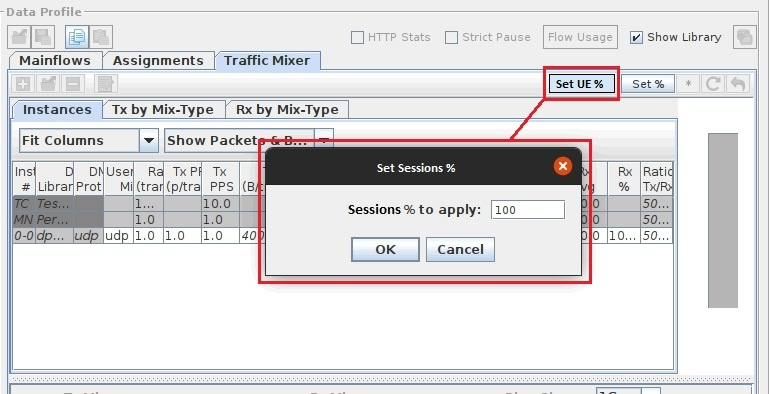
When the test is started in Manual Mode, the Data Tuning tab appears. Initially no UEs are attached. You can start them manually by adjusting the UE % slider bar. The number of UEs running independently can be adjusted for each process. You can also adjust the DMF Rate %. It is initially configured to do 100% of the configured rate. It can be adjusted up to 250% of the configured transaction rate. Thus, if the configured transaction rate is 100 you can increase it to 250. Likewise you can go the other way and reduce the transaction rate. In the Data Traffic Tab - Click on Set UE % to enter the percentage of UEs to actually send data traffic.
Tcl Parameter: DataTuningEn |
|
| SGi PtP Tunneling Support |
Support for SGi PtP tunneling based on UDP. Used to deliver Non-IP data to AS via SGi. Per 3GPP TS 23.401 v 14.3.0. Available in MME Nodal/MME Node when SGW/PGW Node Emulation is enabled. Available in SGW Node when PGW Node Emulation is enabled. Available in PGW Node. Define PtP Tunnel - Access Stratum (Protocol = UDP, Source Port, Destination Port) in Network Devices (MME Nodal, MME Node, PGW Node and SGW Node). Tcl Parameter: SgiPtpTunnelEn |
|
|
Fireball is a DMF threading model that provides optimized performance. This is a licensed feature. Additional details in Fireball Data Message Flows. See this table for supported options. Fireball does not support any Data IPSec test scenario. Fireball does not support ciphering protection and integrity protection for F1UP data - Nas 5G Sm (Include Security Indication), Nas 5G Mm Security Mode ( Integrity Algorithm, Ciphering Algorithm) Fireball does not support fragmentation - Data Message Flow Packet Size
Added support for Vlan IDs when running Fireball. Dynamic VLAN is not supported at this time. Your Test Server must be licensed and configured properly to run Fireball. Go to Test Server Configuration and set Data Gen Performance to Fireball. Go to Managing Test Server Capacity License and select an appropriate License. Contact support with any questions. Next Hop IP Address must be configured. For MME Nodal, the Next Hop IP Address must be configured on the eNodeB User Node. It needs to point at the SGW User Node IP address.
Tcl Parameter: FireballEn |
||
|
CP-CIoT EPS Optimization Supported Ignore RAI T6a Interface S1-U Data Transfer Supported Use Service Request If Apply Activate S1-U Data Transfer Active After (ms)
UP-CIoT EPS Optimization Supported Suspend Context When Idle
NB-IoT Preferred CIoT Send Last Message with RAI Enable ROHC ROHC Profile ID
NB-CIoT Supported on Specific NAS Sessions via TDF
|
Cellular Internet of Things (CIoT) - Cellular network supporting low complexity and low throughput devices for a network of Things. Cellular IoT supports both IP and Non-IP traffic. This is a licensed feature. Cellular IoT EPS Optimizations provide improved support of small data transfer. One optimization is based on User Plane transport of user data and is referred to as User Plane (UP-CIoT EPS Optimization). Another optimization, known as Control Plane (CP-CIoT EPS Optimization), transports user data or SMS messages via MME by encapsulating them in NAS, reducing the total number of control plane messages when handling a short data transaction. These optimizations can be used separately e.g. if the UE or the network supports one of them, or in parallel if the UE and the network supports both. If both the Control Plane and User plane CIoT EPS optimizations are supported for a UE, the PDN connections that only use the Control Plane CIoT EPS Optimization i.e. the MME has included Control Plane Only Indicator in ESM request will only be handled via the Control Plane CIoT EPS optimization. All other PDN connections are handled using Control Plane or User Plane CIoT EPS optimizations. In addition, the Control Plane CIoT optimization can be used to support PDN connections to an SCEF, while regular S1-U data transfer is used independently to support PDN connections to P-GW. All the SGi PDN connections of a UE shall either use S11-U or S1-U at any point in time. The User Plane CIoT EPS Optimization functionality enables support for transfer of user plane data without the need for using the Service Request procedure to establish Access Stratum (AS) context in the serving eNodeB and UE. Additional details in 3GPP TS 24.401 (v13.7.0), TS 24.301 (v13.6.1), 36.413 (v13.3.0) and 29.274 (v13.6.0). Available for Test Activity = (Capacity Test, Session Loading Test, Session Loading with Mobility, Intra-MME, Inter-MME, Command Mode/Sequencer when Handoff Protocol = "None" ) and NAS Tab Version >= 13.6.1 and S1-AP Version >= 13.3.0 (MME Nodal). Available when Mobility = None on MME Node Test Case. Available for Test Activity = Capacity Test or Session Loading Test (SGW Nodal). Available for Test Activity = Capacity Test (gNB CU NSA Nodal). CP-CIoT EPS Optimization Supported - Select to enable Control Plane CIoT EPS Optimization Supported. Available in MME Nodal/Node and SGW Nodal. Tcl Parameter: CpCiotEpsOptimizationEn
Ignore RAI - Available in MME Node test case when Control Plane CIoT EPS Optimization Supported is enabled. Select to ignore the RAI byte. Tcl Parameter: CpCiotIgnoreRai T6a Interface - Available in MME Node test case when Control Plane CIoT EPS Optimization Supported is enabled. Select to support Non-IP Data Delivery (NIDD) through T6a reference point between Mobility Management Entity (MME) and Service Capability Exposure Function (SCEF) for reporting UE Loss of Connectivity, UE reachability, location of the UE and change in location of the UE, and Communication Failure. This capability provides the ability to send data over the control plane (MME/SGSN) in a NAS message, thus reducing the total number of control plane messages required for small data delivery. Click to get additional details on T6a Interface.
S1-U Data Transfer Supported - Available in MME Nodal and MME Node test cases when Control Plane CIoT EPS Optimization Supported is enabled. Select to trigger control plane service flag with active flag for NB-IOT device emulation. Use Service Request If Apply- Available in MME Nodal and MME Node test cases when Control Plane CIoT EPS Optimization Supported and S1-U Data Transfer Supported are enabled. Select for UE Triggered Service Request in Idle Mode (based on 23.401 section 5.3.4.1). Tcl Parameter: CpCiotUseSvcReqEn Activate S1-U Data Transfer - Available in MME Nodal and MME Node test cases when Control Plane CIoT EPS Optimization Supported and S1-U Data Transfer Supported are enabled. Select to activate S1-U data transfer. Enter Active After (ms) - Enter active time in milliseconds. Range: 0 to 65534000, Default = 5000 Tcl Parameter: CpCiotS1uActiveEn Tcl Parameter: CpCiotS1uActiveDelay Tcl Parameter: CpCiotS1uXferEn
UP-CIoT EPS Optimization Supported - Select to enable User Plane CIoT EPS Optimization Supported. Available in MME Nodal/Node. Tcl Parameter: UpCiotEpsOptimizationEn
Suspend Context when Idle - Available when User Plane CIoT EPS Optimization Supported is enabled. Select to suspend context when idle. (UeContextReleaseRequest) Available in MME Nodal. Tcl Parameter: UpCiotIdleSuspendEn
CP-CIoT - Available when Control Plane CIoT EPS Optimization Supported is enabled. Select for CPCIoT indication. Available in SGW Nodal. Tcl Parameter: CpCiotOnlyEn
NB-IoT - Available when Control Plane CIoT EPS Optimization Supported is enabled. Available in MME Nodal. Tcl Parameter: NbIotEn
Narrowband-IoT is a 3GPP Radio Access Technology that forms part of Cellular IoT. It allows access to network services via E-UTRAN with a channel bandwidth limited to 180 kHz (Corresponding to one PRB).
To configure for WideBand IoT (WB-CIoT) : Enable CP-CIoT EPS Optimization Supported and UP-CIoT EPS Optimization Supported and Preferred CIoT = CIoT No Additional Info.
Select to enable Preferred CIoT. Available when Control Plane CIoT EPS Optimization Supported or UP-CIoT EPS Optimization Supported is enabled. Available in MME Nodal. Options: CIoT No Additional Info, CP-CIoT, UP-CIoT. Tcl Parameter: PreferredCiot
Send Last Message with RAI. Available for Test Activity = (Capacity Test, Session Loading Test, Session Loading with Mobility, Intra-MME, Inter-MME, Command Mode/Sequencer when Handoff Protocol = "None" ) and NAS Tab Version >= 13.6.1 and S1-AP Version >= 13.3.0 (MME Nodal). Select for Retrieve UE Info Procedure with RAI (Release Assistance Indication). Only applies to DMF Protocol = ping, raw, udp, tcp, sctp with limited # of transactions. Options: 0, 1, 2
Tcl Parameter: CpCiotSendLastMsgWithRai
Enable ROHC. Available when CP-CIoT EPS Optimization Supported and NB-IOT are enabled and Preferred CIoT = CP-CIoT on MME Nodal test case and when CP-CIoT EPS Optimization Supported is enabled on MME Node Test Case. Select for Robust Header Compression. Select ROHC Profile ID. Options: ROHC_PROFILE_IP (version 1, default ) or ROHCv2_PROFILE_IP
Tcl Parameter: NbIotRohcEn Tcl Parameter: NbIotRohcProfileId
NB-CIoT Supported on Specific NAS Sessions via TDF - Available for Test Activity = (Capacity Test, Session Loading Test, Session Loading with Mobility, Intra-MME, Inter-MME, Command Mode/Sequencer when Handoff Protocol = "None" ) and NAS Tab Version >= 13.6.1 and S1-AP Version >= 13.3.0 (MME Nodal). Not available if CP-CIoT EPS Optimization Supported or UP-CIoT EPS Optimization Supported are enabled. IMSI is used to identify the NAS Session in this TDF. This TDF overlays NAS Sessions with RAT type 0 (NB-CIoT). No other RAT type is currently supported. TACs in this TDF are used for NB-CIoT and should be among the TACs configured by GUI. Multi-TACs can be configured to NB-CIoT. For NAS Sessions not in the TDF, all configurations via the GUI are not changed.
Example tdf file : enbwithdifferentrattype.csv
Tcl Parameter: NbCiotCfgFileEn Tcl Parameter: NbCiotCfgFile |
|
| Enable NetLoc Mode |
Enable Network Location. Available in IMS Node, PCRF Node, PGW Node and SGW Nodal. Follow link for additional information on IMS Node Network Location Support. Follow link for additional information on PCRF Node Network Location Support. Follow link for additional information on PGW Node Network Location Support. Follow link for additional information on SGW Nodal Network Location Support. Tcl Parameter: NetLocEn |
|
| Vo5G |
Select to test the SIP Vo5G feature which supports SIP and RTP-based Voice in the 5G test cases. You are required to configure the following:
|
|
| CSC-4 to Mission Critical CMS |
Available in IP Application Node, MME Nodal, PGW Nodal, SGW Nodal and Wifi Offload Gateway Nodal Test cases. The CSC-4 Interface along with the the CSC-4 APP Tab, TLS Tab and the CSC-4 Flows Tab become available for input. The Landslide VoLTE modules have been enhanced to support configuration management over HTTP for Mission Critical Push-to-Talk (MCPTT) specified in the 3GPP specifications, including TS 23.280, 22.179, 23.179, 24.379, 24.380, 33.179, 24.382, 24.384, etc. The SUT is the EPC core including PCRF. Landslide is used to emulate MC-PTT clients. Mission Critical Push-to-Talk (MC-PTT) is one of important technologies that helps to enable the public safety broadband network proposed by First Responder Network Authority (FirstNet). MCPTT is one of the services under the 3GPP Mission Critical Services (MCS) framework. All of the MCS utilize the MC core provided by 3GPP networks to enable MCS subscribers to communicate with fast setup times, strong security and priority handling. MC services include MCPTT, as well as MC Data, MC Video, etc. The configuration management interface is called CSC-4 and shown in the following diagram from TS 23.280. It is between the Configuration Management Client (CMC) residing in MCPTT UE, and the Configuration Management Server (CMS) within Common Service Core (CSC). It is used to configure MCPTT service, as well as MCData, and MCVideo services. This feature focuses on configuration management in MCPTT services based on On-network model, which includes UE configuration, user profile configuration, service configuration, and group configuration. However, group configuration shown in the diagram is between Group Management Client (GMC) and Group Management Server (GMS) over CSC-5 interface is not currently supported.
Tcl Parameter: MissionCriticalCsc4ClnEn |
|
| NTSR |
Select for Network Triggered Service Restoration (NTSR). Available in MME Nodal (Capacity Test only), MME Node and SGW Node Test cases (disabled if either CUPS (Sxa / Sxb) option is enabled). When NTSR is enabled, the SGW Node will send a DDN (Down Link Data Notification) to the MME when it detects restart via the "restart counter" ( Restart Counter (GTPv2)) in any GTP Signaling message or Echo Request/ Response Message. The Network Devices (NTSR - MMESut_1 and MMESut_2) configured in the SGW Node will be used to pick an MME S11 link to send the DDN Message to. The MME SUT will send a Paging Message upon receipt of the DDN Message to the eNodeB. This will result in the sending of a Service Request Message to the MME to re-establish the session. Tcl Parameter: NtsrEn |
|
| WebRTC |
Available in AMF Nodal, IP Application Node, MME Nodal and Network Host Test cases. Not available when Data Traffic, Data IPSec, External Data, Fireball, VoLTE are selected. The WebRTC Interface along with the the WebRTC, SIP, TLS Tab, OTT Access Auth and the WebRTC Flows Tab become available for input. Control: WebRTC, TLS Tab, TCP. Media: Voice/Video - RTP, Voice/Video - SRTP , MSRP, OTT Access Auth Enable WebRTC for support of WebRTC load testing. Refer to RFC 5389 for Session Traversal Utilities for NAT (STUN) and RFC 6455 for WebSocket Protocol. In the Network Host test case, select either Endpoint or Proxy. When Proxy is enabled, the Media Tab is hidden in the WebRTC.
Available on AMF Nodal Test Configuration. Available on IP Application Node. Available on Network Host (for B2B testing) Available on MME Nodal Test Configuration. Tcl Parameter: WebRtcEn Tcl Parameter: WebRtcGwMode |
|
|
Target N2 IPSec |
Select N2 IPSec to enable IPSec on the N2 Interface. In AMF Nodal / AMF Node testing, select the N2 IPSec option to encapsulate traffic between the gNB and AMF for Control / User Planes. When enabled N2 IPSec becomes available for input on the N2 Interface. N2 IPSec disables N3IWF, TWIF, and 5G-RG on AMF Nodal test case. Select Target N2 IPSec to enable IPSec on the Target N2 Interface. In AMF Nodal , the Target N2 IPSec checkbox is available when Test Activity is with Inter-AMF, Intra-AMF, Command Mode, and Sequencer. Configure parameters on Target N2-IPSec | Target N2-IPSec tab. When enabled the Target N2 IPSec becomes available for input on the Target N2 Interface. Tcl Parameter: GnbAmfIpsecEn Tcl Parameter: TargetGnbAmfIpsecEn |
|
|
Target N3 IPSec |
Select N3 IPSec to enable IPSec on the N3 Interface. In AMF Nodal / AMF Node / UPF Nodal / UPF Node testing, select the N3 IPSec option to encapsulate traffic between the gNB and UPF for Control / User Planes. When enabled N3 IPSec becomes available for input on the N3 Interface. Per (3gpp ts33.501 section 9.3) - 9.3 Security requirements and procedures on N3. N3 is the reference point between the 5G-AN and UPF. It is used to carry user plane data from the UE to the UPF. N3 IPSec disables N3IWF, TWIF, and 5G-RG on AMF Nodal test case. Select Target N3 IPSec to enable IPSec on the Target N3 Interface. In AMF Nodal , the Target N3 IPSec checkbox is available when Test Activity is Inter-AMF, Intra-AMF, Command Mode, and Sequencer. In UPF Nodal, the Target N3 IPSec checkbox is available when Test Activity is Mobility. Configure parameters on Target N3-IPSec | Target N3-IPSec tab. When enabled the Target N3 IPSec becomes available for input on the Target N3 Interface. Tcl Parameter: GnbUpfIpsecEn Tcl Parameter: TargetGnbUpfIpsecEn |
|
| N4 IPSec |
Select N4 IPSec to enable IPSec on the N4 Interface. In AMF Nodal / AMF Node / gNB CU SA Nodal / SMF Node / UPF Nodal / UPF Node testing, select the N4 IPSec option to encapsulate traffic between the gNB and UPF for Control / User Planes. When enabled N4 IPSec becomes available for input on the N4 Interface. In AMF Nodal, SMF/UPF Node Emulation must be enabled for N4 IPSec to become available for selection. Per (3gpp ts33.501 section 9.9) - Security mechanisms for non-SBA interfaces internal to the 5GC and between PLMNs Non-SBA interfaces internal to the 5G Core such as N4 and N9 can be used to transport signalling data as well as privacy sensitive material, such as user and subscription data, or other parameters, such as security keys. Therefore, these interfaces shall be confidentiality, integrity, and replay protected. Roaming interfaces between PLMNs except for N32, shall be confidentiality, integrity, and replay protected. Protection for the N32 interface is specified in clauses 13.1 and 13.2. For the protection of the above mentioned non-SBA internal and roaming interfaces except N32, IPSec ESP and IKEv2 certificate-based authentication shall be supported as specified in sub-clauses 9.1.2 of the present document with confidentiality, integrity and replay protection. This security mechanism shall be used,, unless security is provided by other means, e.g. physical security. A SEG may be used to terminate the IPSec tunnels. QoS related aspects are further described in sub-clause 9.1.3 of the present document. NOTE: It is up to the operator choice to use cryptographic solutions or other mechanisms to protect internal non-SBA interfaces such as N4 and N9. IPSec ESP implementation shall be done according to RFC 4303 [4] as profiled by TS 33.210 [3]. For IPSec implementation, tunnel mode is mandatory to support while transport mode is optional. IKEv2 certificate-based authentication implementation shall be done according to TS 33.310 [5]. The certificates shall be supported according to the profile described by TS 33.310 [5]. IKEv2 shall be supported conforming to the IKEv2 profile described in TS 33.310 [5]. Tcl Parameter: SmfN4IpsecEn |


CDMA2000 Mobile IP Testing
The End-to-End Mobile IP test case tests a minimum of one FA and one HA SUT, and can support testing two FAs and two HA SUTs. Enter the port used by the HA in HA Port Number. The FA port number is defined on the RP tab in the SUT Port Number field.
-
Check the Secondary HA box and select the HA #2 SUT on the Secondary HA sub-tab to enable the second HA.
-
When you use an Inter-PDSN , Inter-PDSN Rate , or Session Loading With Mobility test activity, the handoff FA SUT is defined with the test activity settings.
|
In the CSN Nodal, FA Nodal, and End-to-End Mobile IP test cases, you can use the Dynamic HA checkbox to enable dynamic Home Agent address resolution. When this option is enabled in the End-to-End Mobile IP test case, the HA SUT drop-down list is disabled. Select the Home Agent address to be used in the RRQ from the drop-down list. |
|||
|
In the FA Nodal, HA Nodal and CSN Nodal test cases, you can test using the Mobile IP VPN access model with the MIP IPSec checkbox. In this configuration, one IPSec tunnel is established between either an FA SUT and an HA node (FA Nodal) or an HA SUT and an FA node (HA Nodal) for control plane traffic. Define the IKE settings on the MIP IPSec tab.
|
|||
|
Use the checkbox to enable IPSec between the MN and HA. Define the IPSec settings on the MIPv6 IPSec tab. |
|||
|
Select the LMA Emulation checkbox for control node availability (S2a interface). The Bearer IP Address Pool on the Mobile Subscribers pane is only available when emulation is on. |
|||
|
PMIPv6 Transport |
The PMIPv6 Transport dropdown list is available only when you select the LMA Emulation. When you select Transport as IPv4, you must enter the PMIPv6 Source Address for LMA Node. |
||
|
Use the checkbox to enable IPSec between the SGW/MAG/HSGW and PDN gateway/LMA. Define the IPSec settings on the PMIPv6 IPSec tab.
|
CDMA Femtocell Testing
|
You can use the Femtocell IPSec checkbox to encrypt control plane and user plane traffic between the Femtocell node and Femtocell Gateway SUT. Define the IKE settings on the RP IPSec tab. |
|
|
When auxiliary service instances are supported, you can choose to activate them immediately after the MN's main service instance is activated or activate them when they are needed by a DMF with the Auto-Start Auxiliary Sessions checkbox. You can trigger service instance activation by adding event controls to your DMF. When auxiliary service instances are supported, you can choose to activate them immediately after the MS's main service instance is activated or activate them when they are needed by a DMF by selecting the Auto-Start Auxiliary Sessions checkbox. You can trigger service instance activation by adding event controls to your DMF. See the GPRS section below for the default DMFs that provide this capability. By default, secondary PDP contexts are automatically activated after the associated primary context is activated. When the test includes secondary contexts, you can clear the Auto-Start Secondary Contexts checkbox and trigger activation of secondary contexts from within a DMF with event controls. Three default DMFs that trigger secondary context activation are provided in the Basic Library: |
|
|
Optional in the IPv6 HA Nodal and IPv6 CN Nodal test cases when Data Traffic is included in the test. |
CDMA/WiFI Convergence
|
Select the Initial Network from the dropdown list. This option is available only when you select the Inter Technology Mobility as the Test Activity. Options: CDMA Network, WiMAX Network Default: WiMAX Network Tcl Parameter: InitiateType
|
||
|
Select the MIP Protocol used to define attributes for Mobile IP Registration Request (RRQ) messages (MIPv4) between UE, PDIF-FA's and HA or the types of Mobile IPv6 and ICMPv6 messages the UE will send (MIPv6). Tcl Parameter: MipVersion |
||
|
Route Optimization is optional in the CDMA WiFi Convergence testing when Data Traffic is included on the Test Configuration tab. See also Route Optimization on the Data Traffic tab. Tcl Parameter: Mip6MnRouteOptEn |
||
|
Select MIP IPSec (on the CDMA/WiFi Convergence Test Configuration tab) to encrypt control plane traffic between the MSs and the PDIF-FAs sent to the HA node. See MIP IPSec tab for defining IKE settings. Tcl Parameter: MipIpSecEn |
||
|
In the CDMA/WiFi Convergence test case to select HA Node Emulation to simulate a Home Agent when an HA SUT is not used. You can define Home Agent node on the Network Configurations tab. |
CDMA/WiMAX Convergence Testing
|
Select the Initial Network from the dropdown list. This option is available only when you select the Inter Technology Mobility as the Test Activity. Options: CDMA Network, WiMAX Network Default: WiMAX Network Tcl Parameter: InitiateType
|
||
|
You can use the BS-ASN gateway IPSec to encrypt control plane traffic between the Base Station and ASN nodes. Define the IKE settings on the ASN IPSec tab. |
||
|
When auxiliary service instances are supported, you can choose to activate them immediately after the MS's main service instance is activated or activate them when they are needed by a DMF by selecting the Auto-Start Auxiliary Sessions checkbox. You can trigger service instance activation by adding event controls to your DMF. See the GPRS section below for the default DMFs that provide this capability. By default, secondary PDP contexts are automatically activated after the associated primary context is activated. When the test includes secondary contexts, you can clear the Auto-Start Secondary Contexts checkbox and trigger activation of secondary contexts from within a DMF with event controls. Three default DMFs that trigger secondary context activation are provided in the Basic Library:
|
CDMA2000 Mobile IP Testing
The End-to-End Mobile IP test case tests a minimum of one FA and one HA SUT, and can support testing two FAs and two HA SUTs. Enter the port used by the HA in HA Port Number. The FA port number is defined on the RP tab in the SUT Port Number field.
-
Check the Secondary HA box and select the HA #2 SUT on the Secondary HA sub-tab to enable the second HA.
-
When you use an Inter-PDSN , Inter-PDSN Rate , or Session Loading With Mobility test activity, the handoff FA SUT is defined with the test activity settings.
|
In the CSN Nodal, FA Nodal, and End-to-End Mobile IP test cases, you can use the Dynamic HA checkbox to enable dynamic Home Agent address resolution. When this option is enabled in the End-to-End Mobile IP test case, the HA SUT drop-down list is disabled. Select the Home Agent address to be used in the RRQ from the drop-down list. |
|||
|
In the FA Nodal, HA Nodal and CSN Nodal test cases, you can test using the Mobile IP VPN access model with the MIP IPSec checkbox. In this configuration, one IPSec tunnel is established between either an FA SUT and an HA node (FA Nodal) or an HA SUT and an FA node (HA Nodal) for control plane traffic. Define the IKE settings on the MIP IPSec tab.
|
|||
|
Use the checkbox to enable IPSec between the MN and HA. Define the IPSec settings on the MIPv6 IPSec tab. |
|||
|
Select the LMA Emulation checkbox for control node availability (S2a interface). The Bearer IP Address Pool on the Mobile Subscribers pane is only available when emulation is on. The PMIPv6 Transport dropdown list is available only when you select the LMA Emulation. When you select Transport as IPv4, you must enter the PMIPv6 Source Address for LMA Node. |
|||
|
Use the checkbox to enable IPSec between the SGW/MAG/HSGW and PDN gateway/LMA. Define the IPSec settings on the PMIPv6 IPSec tab.
|
HA Node/Nodal
|
In HA Node test case, select to use Dynamic HA Support to enable dynamic Home Agent address resolution, if you wish to set the address in the initial RRQ to 0.0.0.0. |
|
|
Find MN By NAI |
Select to map NAI to HA and use the TDF on MIP tab |
|
Select to enable DMU (Dynamic Mobile IP Update) - A security feature that allows RSA encryption keys into mobile station to enable secure distribution of mobile IP keys. Tcl Parameter: DmuEn |
|
|
Periodic DMU After Session Established |
Select to enable a DMU update after the session is established. Enter the frequency in the DMU Interval. Available when DMU is enabled. Tcl Parameter: PeriodicDmuEn |
|
DMU Interval (s) |
Enter the interval in seconds when to perform a periodic DMU (Dynamic Mobile IP Update) after the session has been established. Range : 1 to 4000000 Default : 120 Tcl Parameter: DmuInterval |
CDMA2000 Simple IP Testing
In the Simple IP VPN test case, you can test using either the Simple IP VPN or Simple IP VPRN access model.
-
With the VPN model, the same PDSN SUT (RP) is the service node for the MNs and the termination point of the L2TP tunnel.
-
With the VPRN model, two separate PDSN SUTs perform these services. To test with the VPRN model, check the L2TP box and select the SUT that will terminate the L2TP tunnel.
|
The GGSN Nodal test case tests at least one GGSN SUT, and can support testing two GGSNs in a VPRN configuration.
|
|
|
CSN Nodal Testing
Use the CSN Nodal Home Agent System Under Test to encrypt all traffic over the MIP connection.
Select the Home Agent address to be used in the RRQ from the drop-down list.
Select the Enable Dynamic Home Agent check box if you wish to set the address in the initial RRQ to 0.0.0.0.
Select the MIP IPSec checkbox (in the CSN nodal configuration) to encrypt control plane traffic between the ASN-GW and the HA node. See MIP IPSec tab for defining the IKE settings.
|
Select the Initial Network from the dropdown list. This option is available only when you select the Inter Technology Mobility as the Test Activity. Options: CDMA Network, WiMAX Network Default: WiMAX Network
|
|||||||||||||||||||
|
See Test Data Files for further explanation and sample files. If a sample is not found for the specific TDF, you can obtain a sample file from your Technical Support representative. You may also use the following options to select an existing TDF or create/edit TDF-CSV files (TDF-CSV Editor). For most TDF Parameters used for Applying Parameters, each row in the file is the overridden value for a different “Session”, aka a different UE. But some TDFs are done in other dimensions, like Bearers, eNodeBs, Subscribers (2 per UE sometimes) or even Hosts, etc. Tooltips on the TDF Parameter:
Note that the “ID” is a unique ID. Please Provide the ID when reporting issues with a TDF. For TDFs that do not apply / override Parameters, but instead are just their own configuration or data or media files you won’t see TDF ID row details.
|


DCCA Nodal Testing
In DCCA Nodal Testing, use the Diameter IPSec checkbox to encrypt traffic between the Client Node and DCCA SUT. Define the IKE settings on the DCCA-IPSec tab.
|
In both DCCA Nodal and Node test cases, select the Vendor Variant from the drop-down list. Selecting Vendor Variant 1 the Vodafone Options checkbox becomes available. Selecting the Vodafone Options checkbox allows you to enter the relevant configuration parameters on the DCCA App tab in DCCA Nodal and DCCA Node test cases. Tcl Parameter: VendorVariant |
||
|
DCCA Node Testing |
The Diameter IPSec checkbox is available when the test case is set with only a Primary DCCA Node. That is, only when Re-Auth test is not None, Primary/Secondary Proxy check box is not selected, and DCCA Secondary Node is not selected.
|
|
|
Select Affinity Mode to turn on performance improvement of Diameter Applications. Significant performance impact can be achieved with Affinity Mode, especially, when running multiple test cases on the same process. A higher activation rate/throughput can be expected. 5 test cases are optimum as all cores will be used per one process on the C100 S2. Other systems may have a different number of cores per process and the recommended number of test cases should be adjusted accordingly.
|
DCCA Server Node Testing
| Vendor Variant |
In both DCCA Nodal and Node test cases, select the Vendor Variant from the drop-down list. Selecting Vendor Variant 1 the Vodafone Options checkbox becomes available. Selecting the Vodafone Options checkbox allows you to enter the relevant configuration parameters on the DCCA App tab in DCCA Nodal and DCCA Node test cases.
|
||
| Affinity Mode |
Select Affinity Mode to turn on performance improvement of Diameter Applications. Significant performance impact can be achieved with Affinity Mode, especially, when running multiple test cases on the same process. A higher activation rate/throughput can be expected. 5 test cases are optimum as all cores will be used per one process on the C100 S2. Other systems may have a different number of cores per process and the recommended number of test cases should be adjusted accordingly.
|
||
| Re-Authorization Test |
Use the drop-down list to force the server node to send Re-Auth-Requests to the client for all active CC sessions. The client must respond with a Re-Auth-Answer and follow up with an update CCR for that CC session. You can define the starting time and transmission rate for the RAR messages, and choose whether the server node will respond in a positive or negative manner. Options:
Default: None Tcl Parameter: DiaSrvCcReAuth |
||
| Re-Auth Rate |
The rate at which the test attempts to deactivate any active sessions with an ASR message when the test case is stopped. Range: 1 — Variable1 Default: 1 Tcl Parameter: DiaSrvCcAuthRate |
||
| Start Re-Auth |
The number of seconds the node will wait, after all CC sessions are established, before beginning to transmit Re-Auth-Requests. Range: 10 — 65535 Default: 10 1 Maximum rates, number of sessions, and number of emulated nodes vary depending on the test application and the test system's licensed capacity. Tcl Parameter: DiaSrvCcAuthTime |
||
| Primary and Secondary Proxy |
Use the Primary Proxy and Secondary Proxy checkboxes to indicate whether proxies will be emulated.
When you select Primary and Secondary proxy servers, Failover support is available and the settings for the secondary server emulator are enabled.
|
||
| Secondary DCCA Node |
Use Secondary DCCA Node checkbox to allow definition of both the Primary and Secondary Server Nodes. See DCCA Server Node. |
||
| Failover |
When the Node Configuration supports primary and secondary servers or proxies, you can enable or disable failover support. Transport layer failure on the primary node can be simulated at a time that you define. The node notifies the client whether failover is supported or not with the CC-Session-Failover AVP Options: Not Supported or Supported Default: Supported Tcl Parameter: DiaSrvCcFailover |
||
| Simulated Failover |
Use the drop-down list to enable failure simulation. Options: No or Transport Loss Default: No Tcl Parameter: DiaSrvCcFailoverType |
||
| Start Failover |
Use the drop-down list to select the simulated failure trigger. Options:
Default: Before Any Sessions Established Tcl Parameter: DiaSrvCcFailoverStart Tcl Parameter: DiaSrvCcFailoverDelay |
Database Query Node Testing
| LDAP/Ud | Select to configure the LDAP server interface Tcl Parameter : ServerMode |
| DNS | Select to configure the DNS server interface Tcl Parameter: ServerMode |
DHCP Server Node Testing
The DHCP Nodal test configuration allows you to select the test activities and options to set up the interfaces and nodes emulated for the message generation and measurement.
| Process Broadcast DHCP Messages |
Select to process broadcast DHCP messages. Options: True/False Tcl Parameter: ProcessBroadcastMsgEn |
DRA Nodal Testing
The Diameter Routing Agent (DRA) Nodal test configuration allows you to select the test activities and options to set up the interfaces and nodes emulated for the message generation and measurement.
|
Affinity Mode |
Select Affinity Mode to turn on performance improvement of Diameter Applications. Significant performance impact can be achieved with Affinity Mode, especially, when running multiple test cases on the same process. A higher activation rate/throughput can be expected. 5 test cases are optimum as all cores will be used per one process on the C100 S2. Other systems may have a different number of cores per process and the recommended number of test cases should be adjusted accordingly.
|
|||||||||||||||||
|
Enable: Use to indicate whether DRA Nodal will emulate various HSS Interfaces. When selected, LTE Version, the following nodes and interfaces are available for configuration. Tcl Parameter: HssInterfacesEn
Select the required LTE Spec Version from the dropdown list. Options: 8.10.0, 9.2.0, 10.6.0, 11.4.0, 12.10.0, 12.X.0, 13.4 Tcl Parameter: HssLteVersion
Selecting one or more of the Client Interfaces requires you to configure MME/SGSN or AS emulated Nodes. Multiple Destination Host and Realm address is supported. Tcl Parameter: MmeSgsnEn Tcl Parameter: AsEn Tcl Parameter: CscfEn Tcl Parameter: HssScefEn
|
||||||||||||||||||
Select the required LTE Spec Version from the dropdown list. Options: 8.4.0, 8.5.0, 8.6.0, 8.7.0, 8.8.0, 9.4.0, 9.5.0, 9.6.0, 9.7.0, 9.8.0, 9.9.0, 10.6.0, 10.7.0, 10.8.0, 11.4.0, 11.6.0, 12.X.0 Tcl Parameter: PcrfLteVersion
Selecting one or more of the Client Interfaces requires you to configure AGW, AF, BBERF , OCS and TDF emulated Nodes. Multiple Destination Host and Realm address is supported. Tcl Parameter: AgwEn Tcl Parameter: AfEn Tcl Parameter: BberfEn Tcl Parameter: OcsEn Tcl Parameter: TdfEn
|
||||||||||||||||||
|
Enable: Use to indicate whether DRA Nodal will emulate various SCEF Interfaces. When selected, LTE Version, the following nodes and interfaces are available for configuration. Tcl Parameter: ScefInterfacesEn
Select the required LTE Spec Version from the dropdown list. Options: 13.1 Tcl Parameter: ScefLteVersion
Selecting one or more of the Client Interfaces requires you to configure MME/SGSN or AS emulated Nodes. Multiple Destination Host and Realm address is supported. Tcl Parameter: ScefMmeEn Tcl Parameter: ScefSgsnEn
|
||||||||||||||||||
|
Enable: Use to indicate whether DRA Nodal will emulate the Gy OCS Interface. When selected, LTE Version, the following nodes and interfaces are available for configuration. Tcl Parameter: OcsInterfacesEn
Select the required LTE Spec Version from the dropdown list. Options: 9.4.0, 9.5.0, 9.6.0, 9.7.0, 9.8.0, 9.9.0, 10.6.0, 10.7.0, 10.8.0, 11.4.0 Tcl Parameter: OcsLteVersion
Selecting one or more of the Client Interfaces requires you to configure PGW or AS emulated Nodes. Multiple Destination Host and Realm address is supported. Tcl Parameter: OcsPgwEn
|
||||||||||||||||||
|
Enable to configure up to four Interfaces for Client or Server or both. Use the Profile Tab to add commands/Messages and fill them with AVP's from a defined AVP Database. Tcl Parameter: GenInterfacesEn Tcl Parameter: Gen1InterfacesEn Tcl Parameter: Gen1Name Tcl Parameter: Gen1ClnEn Tcl Parameter: Gen1SrvEn Tcl Parameter: Gen2InterfacesEn Tcl Parameter: Gen2Name Tcl Parameter: Gen2ClnEn Tcl Parameter: Gen2SrvEn Tcl Parameter: Gen3InterfacesEn Tcl Parameter: Gen3Name Tcl Parameter: Gen3ClnEn Tcl Parameter: Gen3SrvEn Tcl Parameter: Gen4InterfacesEn Tcl Parameter: Gen4Name Tcl Parameter: Gen4ClnEn Tcl Parameter: Gen4SrvEn |
||||||||||||||||||
|
Select to indicate support for DRA Node failover testing. Tcl Parameter: SecondaryDraEn |
||||||||||||||||||
|
Select Load Balancing option that supports up to 50 million subscribers, only allowing tests in Proxy Mode. Currently only supported on the C100 M2 with Ultra Extreme license. This is a licensed feature. When enabled, able to enter up to 50,000,000 subscribers on the Number of Subscribers field. Tcl Parameter: LoadBalanceEn |
||||||||||||||||||
|
Command Mode/Sequencer |
The Command Mode and Sequencer options are available only when you select Secondary DRA Node, provides you have the appropriate system license. Select Command Mode or Sequencer as required. |
eMBMS Testing
| Mode |
In eMBMS Node test case, there are three emulator modes:
Tcl Parameter : EmulatorMode |
| Test Activity |
Capacity and Session Loading. WedDAV supported for Capacity type test only. |
| Synchronization Interval (Centiseconds) |
Synchronization Interval is the interval that each two continuous synchronization message are transmitted. Range: 1 to 59999 Tcl Parameter: SyncInterval The packets delivered over M1 interface are synchronously transmitted by eNodeBs. In order to support the inter-eNodeB content synchronization, SYNC protocol layer defined between BM-SC to eNB carries additional information that enable eNodeBs to identify the timing for radio frame transmission and detect packet loss. Every packet in M1 contains the SYNC protocol information which is encapsulated at BM-SC. |
| Data Traffic |
In eMBMS Nodal test case, Select Content Type. Tcl Parameter : BmscContentType If Content type = DMF, select to configure streaming IPDV measurement traffic to determine jitter and latency over M1 interface (between eNodeB and MBMS-GW). If Content Type = WebDav, Configure FLUTE Tab and Content WEBDAV tab |
| Emulate Multicast Query |
In eMBMS Node Test case, select to emulate Multicast Query. Set Multicast Query Interval in M1 Interface (IGMP Tab). Not available for standalone BMSC Mode. Tcl Parameter : EmulateMCastQueryEn |
| MB2 |
Select for the MB2 reference point between the GCS AS and the BM-SC. Available on eMBMS Node when eMBMS-GW and BMSC is enabled and on IP Application node when SIP VoIP , GM only and Capacity Test Activity are enabled. On eMBMS Node test case , the GCS-AS SUT is enabled for input. The BMSC MB2-C Node and BMSC MB2-U Node are used for Control and User plane communication between the GCS-AS and the BM-SC. Measurements in MB2 Session, Mb2 Node and Mb2 IP Instance. On IP Application Node test case , the MB2-BMSC SUT is enabled for input. The MB2-C Node and MB2-U Node are used for Control and User plane communication between the GCS-AS and the BM-SC. Measurements in MB2 Session, Mb2 Node and Mb2 IP Instance. According to 3GPP TS 23.468 section 5.1.1, MB2 offers access to the MBMS bearer service from a GCS AS. MB2 carries control plane (MB2-C) and user plane (MB2-U) between GCS-AS and BM-SC.
Figure. 1 Non-roaming architecture from 3GPP TS 23.468 v15.0.0.0. MB2 has the following properties:
Tcl Parameter : Mb2En |
| Maximum Transmission Unit |
The number of bytes at which fragmentation will take place at the bearer plane IP layer. Range from 123 to 9300 Default = 1400 Tcl Parameter : TrafficMtu |
| Support Flute |
Enable to support Flute. Available in eMBMS Nodal, MME Nodal and SGW Nodal test cases. If Flute is supported, treat downlink M1 data as Flute Data and Decode it. If Flute is NOT checked, treat downlink M1 data as RTP data and it is not decoded. Tcl Parameter : EmbmsFluteEn |
| Delay Factor (ms) |
Enter Delay Factor (ms) when Flute is enabled. Used to emulate the data transfer delay via air interface. Available in eMBMS Nodal, MME Nodal and SGW Nodal test cases. Range from 0 to 65535, Default = 0 Tcl Parameter : EmbmsDelayFactor |

eMBMS Common Parameters
gNB CU NSA Nodal
| Inter-CU Initial Type |
Available when Inter-CU Mobility Test Activity is enabled in gNB CU NSA Nodal test case. Click Settings and enter the Inter-CU Mobility settings. Per Spec 3GPP TS 37.340 version 15.6.0 Release/section 10.5 Secondary Node Change (MN/SN initiated). The Secondary Node Change procedure is initiated either by MN or SN and used to transfer a UE context from a source SN to a target SN and to change the SCG configuration in UE from one SN to another. Select : MN-Initiated or SN-Initiated
S1-MME interface with the NAS tab, F1 (F1-AP) and X2-ENB (X2-AP) become available for input. Target gNB DU Control Node , Target gNB DU User Node, (User and Control) Nodes. SUT is gNB CU (Number of Target gNB-CU SUTs) Tcl Parameter : InitType |
| 5GNSA-4G Mobility |
In gNB CU NSA 5GNSA-4G Mobility supports 5G NSA to 4G (eNB) handover as described in spec 3GPP TS 37.340 / section 10.8 Master Node to eNB/gNB Change. You define the S1-MME interface with the NAS tab, F1 with F1-AP, X2-ENB with X2-AP and Target eNodeB Control Node, Target eNodeB User Node, (User and Control) Nodes. SUT is gNB CU (Number of Target gNB-CU SUTs). Click Settings to enter the 5GNSA-4G-Mobility settings. eNB sends out SgNB Release Request when handover happens; Path Switch Request message is sent after received SgNB Release Request Acknowledge; Path Switch Request Acknowledge triggers UE Context Release. Spec 3GPP TS 37.340/section 10.8 Master Node to eNB/gNB Change. 1. Dual Connectivity 5G NSA to 4G eNB -EN-DC:
2. Handover from Dual Connectivity 5G NSA to 5G SA : 10.8.2 MR-DC with 5GC
3. eNB/gNB to Master Node change. Per 3GPP TS 37.340/section 10.9: Click Settings to enter the 5GNSA-4G-Mobility settings. Section 10.9.1 EN-DC - The eNB to Master Node change procedure is used to transfer context data from a source eNB to a target MN that adds an SN during the handover:
Master eNB sends out SgNB Addition Request when handover happens; Path Switch Request message is sent after received SgNB Addition Request Acknowledge; Path Switch Request Acknowledge triggers UE Context Release. |


gNB CU Node
| NSA Mode |
Select NSA Mode for the F1-AP interface between the gNB CU and gNB DU and the X2-ENB interface between the eNobeB and gNB CU. Interfaces F1 (F1-AP) and X2-ENB (X2-AP) become available for input. Nodes gNB CU Control Node and gNB CU User Node are available for input. Fireball is supported in NSA Node.
Tcl Parameter : GnbCuSaMode |
| SA Mode |
Select SA Mode for gNB CU Node to emulate 5G support stand alone (SA) test, through F1-C and F1-U. Interfaces F1 (F1-AP), N2 (NGAP) and N3 (GTPU), AS-5G ( RRC, Message Editor) become available for input. Nodes N2 to AMF and N3 to UPF and AMF SUT are available for input. Fireball is not currently supported in SA Mode. Select either 3GPP or proprietary customer Vendor 1 or proprietary customer Vendor 2, proprietary customer Vendor 3 or proprietary customer Vendor 4. These are the versions and max versions that will be allowed for Vendor 3. Any future version additions with higher values will be blocked at the OK button or Tcl Validate via GUI. CU Node with Vendor 3 or Vendor 4 options: When SA Mode is selected, Enable UE Capability Enquiry on F1-AP is automatically enabled to accommodate additional security mode commands after the initial NAS exchange. For SA Mode = Vendor 2, 'UE Context Setup Request' (code 20) must be configured on F1-AP Message Editor - Json Message Editor.
For SA Mode with Vendor 4 option: For Intra-DU Inter cell Handover. In the Non Vendor 4 implementation the Transmission action indicator is included in message #3 which has to be moved to message#5 as per Vendor 4 requirements (shown below in the code flow below). Also, the SpCell ID is not included in any of the Intra-DU Handover cases. Message #3 includes the target Cell ID in the Special Cell ID IE. Once the transmission action indicator with the value stop is received by the gNB-DU, the source cell traffic is stopped by updating with the DL Data Delivery status of the source cell DRB TEID (message #7). Tcl Parameter : GnbCuSaModeType |
| E1 Interface to CU-UP |
Select for E1 interface to CU-UP Node in SA Mode. When enabled, "Xn Interface" and Fireball are disabled. Only 1 PDU can be configured. One SUT gNB CU-UP SUT can be configured. gNB CU Control Node and gNB CU-CP E1 Node, E1 Interface - E1 Ap Tab becomes available for input. E1-AP Measurements 3GPP 38.401 NG-RAN Architecture Description 3GPP 38.462 E1 Signaling 3GPP 38.463 E1AP
Limitations: Current E1 interface support Landslide capacity test only.
Tcl Parameter : E1ToCuUpEn |
| E1 Interface to CU-CP |
Select for E1 interface to CU-CP Node in SA Mode. See figure 6.1.2-1 for overall architecture and limitations for E1 Interface. When enabled, "Xn Interface" and Fireball are disabled. Only 1 PDU can be configured. One SUT gNB CU-CP SUT can be configured. gNB CU User Node and gNB CU-Up E1 Node, E1 Interface - E1 Ap Tab becomes available for input. E1-AP Measurements 3GPP 38.401 NG-RAN Architecture Description 3GPP 38.462 E1 Signaling 3GPP 38.463 E1AP Tcl Parameter : E1ToCuCpEn |
| Xn Interface |
The Xn interface connects one gNB Node to another gNb Node in NG-RAN (see figure 4.1-1 per 3GPP TS 38.300 V15.5.0); and for separation of control and data, "Xn" is further divided into 2 interfaces: "Xn-C" is for the control messages connecting gNB-CU-CP of gNB-CU nodes and "Xn-U" is for user-plane messages connecting gNB-CU-UP of gNB-CU nodes. The Xn interface is mainly used in handover procedures for information transfer and temporary data forwarding when UE moves away from an area controlled by one gNB node (source node) to a new area controlled by a different gNB node (destination node) - See Figure 9.2.3.2.1-1: Intra-AMF/UPF Handover in 3GPP TS 38.300 V15.5.0); When enabled, Xn-C (Xn Ap Tab), Xn-U (GTPU Tab) , Xn SUT , gNB CU Xn Control Node and gNB CU Xn User node become available for input.
Tcl Parameter : XnEn |
| MR-DC |
Select for Multi-RAT Dual Connectivity (MR-DC) to support S-NG-RAN Node addition. The S-NG-RAN Node Addition procedure is to establish the UE context and relevant resources at the S-NG-RAN node. Added support for M-NG-RAN node initiated S-NG-RAN node Release with / without keeping UE. Available when Xn interface is enabled on the gNB CU node test case. When enabled, the MR DC interface becomes available for input. MN-CU SUT becomes available when gNB Mode = SN. The MN-CU will configure A4 event on the NR Object during the UE attach. When the NR-DC trigger timer expires, the gnb CU Nodal will report the measurement for the A4 event. The MN-CU will fetch the target cell ID and other contents to take actions (Ex: SCG Addition or inter-gnb handover).
The relationship between the PDU session and SDAP is 1:1. The PDCP and DBR is 1:1.
Spec reference : 38.473 F1AP 16.6.0/July 2021 in F1 38.331 RRC 16.5.0/July 2021 in RRC/AS-5G 38.423 XnAp 16.6.0/July 2021 in Xn-C Limitations :
Tcl Parameter : GnbCuMrDcEn |
| Data Forwarding for Mobility |
Data Forwarding for Mobility has been moved to N2|NGAP's "Direct Forwarding" checkbox with Tcl variable upgrade. Available when SA Mode is enabled. Select to support Xn HO with data forwarding. |
| Command Mode |
When "Command Mode" is "Enabled" and the test case is running, a "Command" button appears under the "Emulator Configuration" by the Mobile Subscribers section. Select to trigger Reset in Command Mode. Click the Command button on the X2-AP to execute the Reset Command. |


gNB CU SA Nodal
| Vendor Variant |
Select either 3GPP or proprietary customer Vendor 1 or proprietary customer Vendor 2, proprietary customer Vendor 3, or proprietary customer Vendor 4 . When "Vendor 3" is selected, only "15.3.0/Sep2018" and "15.7.0/Oct2019" are available under the "Version (38.473)" dropdown list under the F1 (F1-AP). These are the versions and max versions that will be allowed for Vendor 3. Any future version additions with higher values will be blocked at the OK button or Tcl Validate via GUI. SA Nodal with Vendor 3 option: When "Vendor 3" is selected, the intra-DU inter-cell handover message flow will be as follows :
Note: Message 5 is changed from DL RRC Message Transfer to UE Context Modification Request, and message 5.1 (UE Context Modification Response) is added. SA Nodal with Vendor 4 option: For Intra-DU Inter cell Handover. In the Non Vendor 4 implementation the Transmission action indicator is included in message #3 which has to be moved to message#5 as per Vendor 4 requirements (shown below in the code flow below). Also, the SpCell ID is not included in any of the Intra-DU Handover cases. Message #3 includes the target Cell ID in the Special Cell ID IE. Once the transmission action indicator with the value stop is received by the gNB-DU, the source cell traffic is stopped by updating with the DL Data Delivery status of the source cell DRB TEID (message #7).
Tcl Parameter: VendorVariant |
| Initial Network |
Available when Test Activity = Inter Technology Mobility. Select Initial Network from dropdown list. Options: 5GS Initial Network indicates where the UE will initially attach / register. Select the Handoff Protocol below to indicate the "Target" network. For example: Initial Network = 5GS , Handoff Protocol = LTE (which is the Target). The UEs will initially attach / register to 5GS then handoff to LTE. The F2 Help key has been enhanced to indicate which network is the Target.
Tcl Parameter : InitiateType |
| Handoff Protocol |
Available when Test Activity = Inter Technology Mobility. When Handoff protocol = LTE, the S1-MME becomes available for input. EPS Pane is enabled. Options : LTE 3GPP 23.501, 23.502, 38.413, 24.501, 33.501, 38.473, 38.331, 36.413 O-RAN.WG5.C.1-v07.00
Inter RAT Handover to LTE message flow is listed below in section Handoff Type. Tcl Parameter : HandoffProtocol |
| Handoff Type |
Available when Test Activity = Inter Technology Mobility. When Handoff protocol = LTE, the S1-MME becomes available for input. EPS Pane is enabled. Inter RAT Handover to LTE procedure, Options : Handover, REG/TAU 3GPP 23.501, 23.502, 38.413, 24.501, 33.501, 38.473, 38.331, 36.413 O-RAN.WG5.C.1-v07.00 Inter RAT Handover to LTE message flow: Figure 6.8.1.1-1: Inter RAT Handover to LTE message flow (O-RAN.WG5.C.1-v 07.00) 5GS to EPS handover using N26 interface (23.502)
Tcl Parameter : HandoffType |
| AMF/SMF Node Emulation |
Select for AMF/SMF Node Emulation within gNB CU SA Nodal. SUT UPF , SMF N4 Node , SMF N4 GTP Node become available for configuration. Interface CN NAS-5G includes 2 sub-tabs: Nas 5G Sm (SM) and Nas 5G Mm (MM). Interface N2 includes 2 sub-tabs : (NGAP) and (SCTP) Interface N4 (PFCP (UPF and SMF) and N4 IPSec Tcl Parameter: AmfSmfNodeEmulationEn |
| UPF Node Emulation |
Select for UPF emulation within gNB CU SA Nodal. The N4 (PFCP ) and N6 (N6 Data Traffic) interfaces become available as well as UPF N3 Node, ,UPF N4 Node and UPF N4 GTP Node. Tcl Parameter: UpfNodeEmulationEn |
| PGW-C Emulation |
Select for PGW-C Emulation. The S2a/S2b/S5/S8 (GTPv2) interface becomes available for input. Enter the EPS Dedicated Bearers per Default. Requires AMF/SMF Node Emulation. Tcl Parameter: PgwCEmulationEn |
| PGW-U Emulation |
PGW-U Emulation checkbox was added to gNB CU SA Nodal for 5G/4G mobility scenarios. Select PGW-U Emulation for UPF Node to internally allocate additional map space to accommodate multiple TEIDs (4G Uplink) per PFCP Session. Only available for selection when UPF Node Emulation is enabled. Tcl Parameter: PgwUEmulationEn |
| N26 Interface |
Select for N26 Interface - Requires AMF/SMF Node Emulation. Additional details here - N26 Interface |
| Emergency Alert |
Select for Emergency Alert - Requires AMF/SMF Node Emulation. Additional details here - Emergeny Alert |
| N4 IPSec |
Select for N4 IPSec - Requires AMF/SMF Node Emulation or UPF Node Emulation. Disabled for both together. Disabled for N26 Interface with PGW-C Emulation. Additional details here - N4 IPSec |


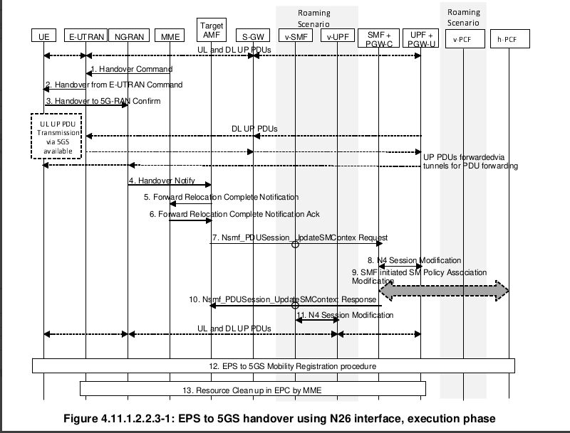
LCS Testing
| Slg |
Selecting Slg provides the Slg interface tab in LCS Node/Nodal test cases for EPC location services between GMLC and MME. Tcl Parameter : SlgEn |
| Slh |
Selecting Slh provides the Slh interface tab in LCS Node/Nodal test case for GMLC to request routing information from the HSS/HLR. Tcl Parameter : SlhEn |
| Sls |
Selecting Sls provides the Sls interface tab in LCS Node/Nodal and MME Node/Nodal test cases for MME to request location information from the e-SMLC. Tcl Parameter : SLsgEn |
| E2 |
Selecting E2 provides the E2 interface tab in LCS Node and PSAP Node test cases. LCS Node test case can be used to emulate a GMLC instance and an E2 interface for interacting with an external PSAP. Per reference docs : NENA-05-001 December 2003 (NENA Standard for the Implementation of the Wireless Emergency Service Protocol E2 Interface) and J-STD-036-A - Enhanced Wireless 9-1-1 Phase 2 Tcl Parameter : E2En |
GPRS Testing
In the GGSN Nodal test case, you can configure the test for an L2TP VPN access model with the Security Gateway checkbox. When you enable the gateway, you can define the Security Gateway node and the L2TP and PPP-L2TP tabs are added to the test case to define the L2TP tunnel and the PPP sessions within the tunnel. In this configuration, the Security Gateway is responsible for assigning IP addresses to the PDP contexts. Define an address pool on the Mobile Subscriber pane.
You can also define a GGSN LAC SUT for VPRN testing.
|
IMPORTANT: When testing in an L2TP VPN configuration, the PDP Type must be PPP. |
| Auto-Start Secondary Contexts |
When auxiliary service instances are supported, you can choose to activate them immediately after the MS's main service instance is activated or activate them when they are needed by a DMF by selecting the Auto-Start Auxiliary Sessions checkbox. You can trigger service instance activation by adding event controls to your DMF. See the GPRS section below for the default DMFs that provide this capability. By default, secondary PDP contexts are automatically activated after the associated primary context is activated. When the test includes secondary contexts, you can clear the Auto-Start Secondary Contexts checkbox and trigger activation of secondary contexts from within a DMF with event controls. Three default DMFs that trigger secondary context activation are provided in the Basic Library:
|
| Network Requested Secondary PDP Context Activation |
The parameter is available when GTP Version > 0 (on the GTP tab) and Number of Secondary PDP Contexts is > 0 (on the Mobile Subscriber pane). Type: True/False Default: False Tcl Parameter: NetReqSecPdpActEn
|
| Initiate Delete PDP Context |
During GGSN Node testing, when you select Initiate Delete PDP Context the GGSN sends a Delete PDP Context Request to the SGSN, triggering the SGSN to release the context and tear down its tunnel with the GGSN. Upon completion, the SGSN replies with a Delete PDP Context Accept, allowing the GGSN to tear down its tunnel with the SGSN. The Delete Timer(s) is available when you select Initiate Delete PDP Context. The value set in this field determines how long a successful PDP session will be active before the Delete PDP Context Request is sent. |
| APN DNS Lookup |
In GPRS testing, select the APN DNS Lookup checkbox to allow SGSNs to make a DNS query for the APN name to determine the GGSN address and forward the PDP contexts create request accordingly. When you select the APN DNS Lookup checkbox, the APN DNS Lookup parameters on the Network Devices tab becomes available. |
| L2TP VPN Configuration |
During GGSN Node testing, selecting L2TP VPN configuration makes the Security Gateway responsible for assigning IP addresses to PDP contexts. |
| QOS Updates |
Use QOS Updates to change a context's address or its QOS profile with GGSN-initiated PDP context updates when you select QOS Updates. Define update frequency and content on the QOS Update tab. |
HNB Testing
| Core Network |
Select either PS Domain or CS Domain (Voice over Iuh) or PS & CS Domain PS Domain (Iuh interface - SM/GMM Tabs become available) CS Domain (Iuh interface - MM/CC Tabs become available, Rtpvoice used to emulate voice traffic) PS & CS Domain (Iuh interface - SM/GMM and MM/CC Tabs become available, Rtpvoice used to emulate voice traffic) |
|
| Auto-Start Secondary Contexts |
By default, secondary PDP contexts are automatically activated after the associated primary context is activated. When the test includes secondary contexts, you can clear the Auto-Start Secondary Contexts checkbox and trigger activation of secondary contexts from within a DMF with event controls. Three default DMFs that trigger secondary context activation are provided in the Basic Library: |
|
| Activate PDP Contexts upon GMM Attach Deactivate PDP Contexts upon GMM Attach |
When you select the checkbox (default setting), the test will attempt to activate the number of PDP contexts defined on the Mobile Subscribers pane after an MN successfully attaches to the SGSN SUT. When you clear the checkbox, the test will only perform attaches and detaches with the SGSN.
|
|
| Initial Network |
Select Initial Network from the dropdown list. This option is available only when you select "Inter Macro-HNB Mobility". Options: HNB, Macro (default) Tcl Parameter: InitiateType |
|
| HNB GW DNS Lookup |
In HNB testing, select the HNB GW DNS Lookup checkbox to allow SGSNs to make a DNS query for the DNS name to determine the GGSN address and forward the PDP contexts create request accordingly. When you select the HNB GW DNS Lookup checkbox, the HNB GW DNS Lookup parameters on the Network Devices tab becomes available. |
|
| HNB IPSec |
You can use the HNB IPSec checkbox to encrypt control plane traffic between the UE/HNB and HNB GW. |
|
| Target HNB IPSec |
The Target HNB IPSec checkbox becomes available when the Test Activity is Session Loading With Mobility or Intra-HNB GW Mobility. |
|
| 3G Macro RNC Emulation |
Available when Test Activity = Capacity. Enables the Iu-PS (PS Domain), Iu-CS (CS Domain) or both (PS & CS Domain) interfaces. Support for HHO, connected mode, Intra HNB-GW mobility per 3GPP TS 25.467 (release 9) Tcl Parameter: MacroRncEmulationEn |
|
| Perform LAU After Handoff |
The Perform LAU After Handoff becomes available when the Test Activity is Session Loading With Mobility or Intra-HNB GW Mobility and CS Domain is selected. Tcl Parameter: MobLauEn Enter TAU Delay (ms) - Default = 1000 Tcl Parameter: MobLauDelay |
|
| Relocation Type |
Relocation Type becomes available when the Test Activity is Session Loading With Mobility or Intra-HNB GW Mobility on HNB GW Nodal TC. Also available on MSC Node and SGSN Node Test cases. If UE Involved is selected, the Target Cell Id will be available in the id-RelocationPreparation RANAP Message. Options: UE Not Involved or UE Involved (default) Tcl Parameter: RelocationType |
|
| CN Involved |
CN Involved becomes available when the Test Activity is Session Loading With Mobility or Intra-HNB GW Mobility. Support for mobility with CN involved. Support for Intra-HNB in SSGN and MSC Emulator configurations. Tcl Parameter: CnInvolvedEn |
HSGW Nodal Testing
|
Select the Initial Network from the dropdown list. This option is available only when you select the Inter Technology Mobility as the Test Activity. Options: CDMA, LTE Default: CDMA Tcl parameter: InitiateType |
|||
| SGW Node Emulation | Select SGW Node Emulation, available when Test Activity is Inter Technology Mobility, to enable the S11 interface between the MME SUT and the emulated Serving Gateway. In addition, SGW GTP Node, SGW User Node and SGW MAG Node become available for configuration.
If you do not select SGW Node Emulation, you would need to add the SGW Node test case, which provides a way to interface/communicate with the HSGW Node via the Use IMSI as NAI User and Use APN as NAI Domain parameters (in SGW Node test case). |
||
Available when Test Activity is Inter Technology Mobility and LMA Node Emulation is not selected. Select to indicate Optimized Handoff from LTE to eHRPD, with Multi-PDNs and also in both Active Mode and Idle Mode (Handoff In Idle Mode).
Use the checkbox to select the Target MME S101 SUT and configure on the Network Devices tab for optimized handoff. Also configure:
|
|||
|
Available (if you system is licensed for LTE) when the Test Activity is Inter Technology Mobility or Session Loading with Mobility and the Mobility Type is Inter Technology. Tcl Parameter: PartialContextHandoffEn
Partial Context Handoff specifies that when the UE returns to HSGW to resume the existing session, the PDN connections are created only per the existing context UE has on network. Similarly, bearers are established to match those that were available on the network. (Since the HSGW has partial context for the UE, it reduces the delay before the UE can send and receive packets.) |
|||
|
UE Context Maintenance timer |
In HSGW Node test case, The UE Context Maintenance Timer (s) is available accessible only when you select Mobility Support as Inter-Technology.
|
||
|
Available when Test Activity is Inter Technology Mobility and when Aux Srv Instances per Subscriber is > 0. The TFT Settings are only also enabled when Aux Srv Instances per Subscriber is > 0. |
|||
|
|
Available when Test Activity is Inter Technology Mobility and Mobility is Inter-Technology in Nodal and Node test cases. Default value is None. |
||
|
|
The Handoff Mode is available only when you select the Inter-HSGW as the Test Activity. Select the handoff mode With Context Transfer or Without Context Transfer (default). Selecting the With Context Transfer radio button allows you to enter the UE Aquisition Time. Tcl Parameter: UeAcqTime |
||
|
|
Select LMA Node Emulation for control node availability (S2a interface). The Home Address Type and Bearer IP Address Pool on the Mobile Subscribers pane are available only when you select LMA Node Emulation. LMA Node also become available for configuration.
|
||
| The PMIPv6 Transport dropdown list is available only when you select the LMA Node Emulation. When you select Transport as IPv4, you must enter the PMIPv6 Source Address for LMA Node. | |||
| PMIPv6 IPSec |
Use the checkbox to enable IPSec encapsulation between the SGW/MAG/HSGW and LMA. Define the IPSec settings on the PMIPv6 IPSec tab. |
||
|
When auxiliary service instances are supported, you can choose to activate them immediately after the MS's main service instance is activated or activate them when they are needed by a DMF by selecting the Auto-Start Auxiliary Sessions checkbox. You can trigger service instance activation by adding event controls to your DMF. See the GPRS section below for the default DMFs that provide this capability. By default, secondary PDP contexts are automatically activated after the associated primary context is activated. When the test includes secondary contexts, you can clear the Auto-Start Secondary Contexts checkbox and trigger activation of secondary contexts from within a DMF with event controls. Three default DMFs that trigger secondary context activation are provided in the Basic Library: |
|||
| Data Forwarding |
Available when Test Activity is Inter Technology Mobility and Optimized Handoff is selected (LMA Node Emulation is not selected). Select to indicate Data Forwarding is supported during Optimized Handoff from LTE to eHRPD. |
||
| Handoff In Idle Mode |
Available when Test Activity is Inter Technology Mobility and Optimized Handoff is selected (LMA Node Emulation is not selected). Select to indicate Handoff In Idle Mode is supported during Optimized Handoff from LTE to eHRPD. |
HSS Nodal Testing
| Affinity Mode |
Select Affinity Mode to turn on performance improvement of Diameter Applications. Significant performance impact can be achieved with Affinity Mode, especially, when running multiple test cases on the same process. A higher activation rate/throughput can be expected. 5 test cases are optimum as all cores will be used per one process on the C100 S2. Other systems may have a different number of cores per process and the recommended number of test cases should be adjusted accordingly.
|
|
| HSS-MME/SGSN I/F S6a | Selecting S6a provides the S6a interface tab in HSS Nodal test case for authenticating/authorizing user access to the evolved system (AAA interface) between MME and HSS. Select HSS-MME/SGSN I/F and either S6a or S6d or Gr interface. Mutually exclusive with LDAP I/F. Tcl Parameter: HssIfEn Tcl Parameter: HssClnInterface | |
| HSS-MME/SGSN I/F S6d | Selecting S6a provides the S6a interface tab in HSS Nodal test case for authenticating/authorizing user access to the evolved system (AAA interface) between SGSN and HSS. Select HSS-MME/SGSN I/F and either S6a or S6d or Gr interface. Mutually exclusive with LDAP I/F. | |
| HSS-MME/SGSN I/F Gr | Selecting the Gr radio button provides the Gr interface tab in HSS Nodal test case to test communication between SGSN and HSS. Select HSS-MME/SGSN I/F and either S6a or S6d or Gr interface. Mutually exclusive with LDAP I/F. | |
| HSS-IMS I/F Sh | Select to configure the Sh interface between the Application Server (AS) and the HSS. Sh interface is used for storing, retrieving and modifying user data. User profile can be enabled via Sh interface. Available when LTE Spec Version > = 11.4.0 and for Capacity Test and Session Loading Test. Mutually exclusive with LDAP I/F. Tcl Parameter: ImsIfEn Tcl Parameter: HssShEn | |
| HSS-IMS I/F Cx | Select to configure the Cx interface between the CSCF (Call Session Control function) and the HSS. User Profile tab can be enabled via Cx interface. Available when LTE Spec Version > = 11.4.0 and for Capacity Test and Session Loading Test. Mutually exclusive with LDAP I/F. Tcl Parameter: HssCxEn | |
| EIR I/F S13 | Select to configure S13 interface, EIR database/HSS for transfer of subscription and authentication data between MME and HSS. Available for Capacity Test and Session Loading Test. Mutually exclusive with LDAP I/F and S13'. Tcl Parameter: EirIfEn Tcl Parameter: EirClnInterface | |
| EIR I/F S13' | Select to configure S13' interface between SGSN and EIR database/HSS for transfer of subscription and authentication data between SGSN and HSS. Available for Capacity Test and Session Loading Test. Mutually exclusive with LDAP I/F and S13. | |
| CBC I/F SBc | Select to configure the CBC interface used for Public Warning message delivery. Available for Capacity Test and Session Loading Test. Mutually exclusive with LDAP I/F. Tcl Parameter: CbcIfEn | |
| LDAP I/F Ud | Select to configure the LDAP client interface. Mutually exclusive with all other Emulated Interfaces. Cannot enable any other interfaces when you select LDAP I/F U/D. Available for Capacity Test and Session Loading Test. Tcl Parameter: LdapIfEn | |
| Signaling Bearer | The Signaling Bearer dropdown list, available when you select the Gr radio button, indicates signaling protocols used between 2 entities for transporting SS7 messages (i.e., MAP). | |
| LTE Spec Version |
Use to specify a release version of 3GPP specification which HSS Nodal uses for constructing or interpreting messages. Select the required LTE Spec Version from the dropdown list. Options: 8.10.0, 9.2.0, 10.6.0, 11.4.0, 12.10.0, 12.X.0 Tcl Parameter: LteVersion |
|
| Target Emulated Interfaces |
Available when Test Activity = Mobility. Support for handover scenarios: HSS-MME/SGSN/IF. S6a -> S6a, S6d -> S6d, Gr -> Gr, S6a -> Gr, S6a -> S6d. Mobility is not supported between S6d and Gr. Other interfaces are disabled , except S6a, S6d and Gr, when Mobility is selected. Options: S6a, S6d, Gr Tcl Parameter: MobHssClnInterface Authentication After Handoff Tcl Parameter: AuthAfterHoEn |
HSS Node Testing
| Affinity Mode |
Select Affinity Mode to turn on performance improvement of Diameter Applications. Significant performance impact can be achieved with Affinity Mode, especially, when running multiple test cases on the same process. A higher activation rate/throughput can be expected. 5 test cases are optimum as all cores will be used per one process on the C100 S2. Other systems may have a different number of cores per process and the recommended number of test cases should be adjusted accordingly.
|
||||||||||||
| S6a |
Selecting S6a provides the S6a interface tab in HSS Node test case for authenticating/authorizing user access to the evolved system (AAA interface) between MME and HSS. Tcl Parameter: HssSrvS6aEn |
||||||||||||
| S6c | S6c is a diameter interface that carries routing information between an HSS and an SMS-GMSC. When an SMS message is being sent to a mobile subscriber via the SGd interface, the SMS-GMSC sends an S6c routing info request (Send-Routing-Info-for-SM-Request) to the HSS to determine on which MME the destination subscriber is registered. The HSS responds with routing information that the SMS-GMSC uses to send the SMS message towards the correct MME. The HSS determines the routing information to send using information it receives over the S6a interface (when the MME sends an Update Location Request to the HSS). Only available when S6a interface is enabled. Support for MME SMS registration is added to the existing HSS S6a feature. In a received Update Location Request message, the emulated HSS looks for the indicators to determine if the MME is registering for SMS. The HSS will respond with the SMS registered bit set in the ULA flags if the MME is successfully registered for SMS service. All subscribers that are associated with the MME are registered for SMS service. (Only one ULR request needs to contain the MME SMS registration info for all UE’s to receive SMS messages via that MME).
The main applicable reference specs are: 3GPP TS 29.338 (14.1.0) – this defines the Diameter based interfaces specific to SMS when used with SMS in MME architecture. This includes the S6c, SGd, and Gdd interfaces. The Gdd interface is not applicable. 3GPP TS 29.272 (15.6.0) defines the S6a interface. Tcl Parameter: HssSrvS6cEn |
||||||||||||
| S6d |
Selecting S6d provides the S6d interface tab in HSS Node test case for authenticating/authorizing user access to the evolved system (AAA interface) between SGSN and HSS. Tcl Parameter: HssSrvS6dEn |
||||||||||||
| Gr |
Selecting the Gr radio button provides the Gr interface tab in HSS Node test case to test communication between SGSN and HSS. Tcl Parameter: HssSrvGrEn |
||||||||||||
| SWx |
Selecting the SWx radio button provides SWx interface between 3GPP AAA Server and HSS Node is used for transport of authentication, subscription and PDN connection related data. Tcl Parameter: HssSrvSwxEn |
||||||||||||
| S13 |
Select to configure S13 interface, EIR database/HSS for transfer of subscription and authentication data between MME and HSS. Tcl Parameter: EirSrvMmeEn |
||||||||||||
| S13' |
Select to configure S13' interface between SGSN and EIR database/HSS for transfer of subscription and authentication data between SGSN and HSS. Tcl Parameter: EirSrvSgsnEn |
||||||||||||
| SBc |
Select to configure the CBC interface used for Public Warning message delivery. Tcl Parameter: CbcSrvEn |
||||||||||||
| CX |
Select to configure the Cx interface between the CSCF (Call Session Control function) and the HSS. User Profile tab can be enabled via Cx interface. Available when LTE Spec Version > = 11.4.0 Cx Interface is also available on IMS Node test case. Tcl Parameter: HssSrvCxEn |
||||||||||||
| Sh |
Select to configure the Sh interface between the Application Server (AS) and the HSS. Sh interface is used for storing, retrieving and modifying user data. User profile can be enabled via Sh interface. Available when LTE Spec Version > = 11.4.0 Tcl Parameter: HssSrvShEn |
||||||||||||
|
S6t |
Select to configure the S6t interface used between the HSS and SCEF (Services Capability Exposure Function). LTE Spec Version = 13.4.0 or 15.X.0. Added inter-working with S6a in release 17.4, LTE Spec Version must be > or = 15.X.0 for both S6a and S6t checkboxes to become available for interoperability testing. Command Mode is not available with S6t interface. Must enter at least one MSISDN or an External Identifier when S6t Interface is enabled. Tcl Parameter: HssSrvS6tEn |
||||||||||||
| Wx |
Select to configure the Wx interface used between the HSS and 3GPP AAA. Available when LTE Spec Version = 11.2.0 Tcl Parameter: HssSrvWxEn |
||||||||||||
| SLh |
Select to configure the SLh interface used between HSS and GMLC. Tcl Parameter: HssSrvSlhEn |
||||||||||||
| Zh |
Available when LTE Spec Version > = 11.4.0 and <= 12.X.0. The purpose of Zh interface is to perform the retrieval of an authentication vector and possibly GBA User Security Setting (GUSS ) from the HSS. The reference point Zh used between the BSF and the HSS allows the BSF (Boot Strapping Function) to fetch the required authentication information and all GBA user security settings (GUSS) from the HSS. The reference point Zh is an intra-operator domain interface. Zh interface will be introduced on top of existing diameter based implementation of IMS Cx interface as depicted in Figure 1 below.
Tcl Parameter: HssSrvZhEn |
||||||||||||
|
NRF Interface |
Select to add UDM (Nudm Interface) capabilities to HSS Node to support 4G to 5G mobility including EPS fallback testing. Expose:
Select to emulate UDM (Nudm)- Unified Data Management Function. Interface Nudm (Nudm NF Tab - NF Producer) becomes available for input. UDM SBI Node is available for input. Starting SUPI, Starting GPSI, IMEI, Software Version Reference is 3GPP TS 23.632 V16.1.0 Architecture: Architecture for Direct UDM-HSS interworking in reference point representation:
Supported Procedure: Authentication (reference section 5.2/3GPP TS 23.632 V16.1.0)
5GC-EPC Mobility (reference section 5.3/3GPP TS 23.632 V16.1.0) ** As defined in 3GPP TS 23.501 [2], when interworking procedures with N26 are used, the UE operates in single-registration mode. For the 3GPP access, either the AMF or the MME is registered in the HSS+UDM.
1. Mobility from 5GC to EPC, with N26 ( *(reference section 5.3.2/3GPP TS 23.632 V16.1.0)* Figure 5.3.2-1 shows the interaction between the HSS and UDM in an interworking scenario with N26, when the UE attaches to the EPC. Supported Procedure:
Procedure [3] and [4] are not require since Landslide emulates both UDM & HSS on HSS Node.
2. Mobility from EPC to 5GC, with N26 (reference section 5.3.3/3GPP TS 23.632 V16.1.0) Figure 5.3.3-1 shows the interaction between the UDM and the HSS in an interworking scenario with N26, when the UE attaches to the 5GC.
Supported Procedure:
When NRF Interface is enabled on HSS Node, the UDM Registration to NRF procedure is performed once HSS is started . Per 3GPP TS 29.510, Section 5.2.2.2.2 (Figure 5.2.2.2.2-1 NF Instance Registration). In addition, NF Heart-Beat (Figure 5.2.2.3.2-1 NF Heart-Beat) is performed periodically after successful registration. Procedure NF Instance Deregistration ((Figure 5.2.2.4.1-1 NF Instance Deregistration) is performed during de-registration. When NRF Interface is enabled on HSS Node, Interface Nnrf Client (NF Consumer) , SUT NRF SBI (Network Devices) and NRF SBI Node become available for input.
|
||||||||||||
| Signaling Bearer | The Signaling Bearer dropdown list, available when you select the Gr radio button, indicates signaling protocols used between 2 entities for transporting SS7 messages (i.e., MAP). | ||||||||||||
| LTE Spec Version |
Use to specify a release version of 3GPP specification which HSS Node uses for constructing or interpreting messages. Select the required LTE Spec Version from the dropdown list. Options: 8.4.0, 8.10.0, 9.2.0, 10.6.0, 11.2.0, 11.4.0, 12.10.0, 12.X.0, 13.4.0 (S6t interface only), 15.X.0 (S6a Interface only), 16.1.0 Tcl Parameter: LteVersion |
||||||||||||
| SCTP Command Mode | Internal use. | ||||||||||||
| Command Mode |
See HSS Node Command Mode test case. Command Mode option is not available when you select only SWx interface as the IDR and DSR commands are not applicable to the SWx interface command set. |


IMS Nodal Testing
|
Test Activity |
Select Capacity Test, Session Loading Test or Inter Technology Mobility. |
|
Handoff Protocol |
Available when Test Activity = Inter Technology Mobility. Select for E-SRVCC (Single Radio Voice Call Continuity) procedure. New Tabs, ISC-PS and ISC-CS, are enabled for Signaling flows. AS, AS Port and AS Host become available in Network Devices as well as S-CSCF Node and ATGW Node. The Inter-Technology Mobility Settings dialog supports "Single Handoff" only: See Flow - Boxes with Black text is depicting PS Subscriber, Boxes with Green text is depicting the paired CS Subscriber: Reference documents:
This is a licensed feature. Option = E-SRVCC Tcl Parameter: HandoffProtocol |
|
Core Network PS Domain Mw ISC Mx Ml Generic CS Domain Nc |
Select to either PS (Packet Switched) or CS (Circuit Switched) domain.
Tcl Parameter: MsNetwork |
|
Available when PS Domain Generic Interface is enabled. In IMS Nodal test case, the Generic interface allows you to configure testing of an IMS Interface. Enter the Generic Interface Name. The Generic Interface name (If Test1 is used) will be populated on the Test Node Tab (GEN-Test1 Node), the RTP Traffic tab ( GEN-Test1 RTP Traffic), and the SIP OM tabs (e.g. GEN-Test1|Main, GEN-Test1|1xx, etc). Enter up to 8 letters, number or '_'. The first character must be a letter. Configure:
The Generic Interface can used to emulate Mg and Mj interfaces for X-CSCF testing. Mj interface uses SIP over UDP or TCP , BGCF to MGCF or MGCF to BGCF per 3GPP 23.002, 23.228, 24.229, 29.163. Mg interface uses SIP over UDP, MGCF to I-CSCF per 3GPP 23.002, 23.228, 24.229. Tcl Parameter: GenericName |

IMS Node Testing
|
Indicates the Test Activity performed in IMS Node test case. Command Mode/Sequencer available.
|
||
|
SIP Endpoint Proxy B2BUA |
Select to indicate whether IMS Node emulates SIP Endpoints, SIP Proxy or Back-to-Back User Agent (B2BUA).
Selecting Proxy allows you to also select Enable Separate Registrar to receive register requests. Selecting Enable Separate Registrar ensures the REGISTER requests goes to the registrar and INVITE requests will go to proxy.
Tcl Parameter: ImsMode |
|
|
|
Select either the Gm, Mw (P-CSCF testing), ISC (S-CSCF/I-CSCF Testing), Mx Interface (CSCF/BGCF and IBCF Testing) or Ml (E-CSCF and GMLC Testing). Additional information in IMS Nodal/Node Test Case. Tcl Parameter: ImsInterface |
|
|
Select to enable the I2 interface. Tcl Parameter: ImsNodeI2En |
||
|
Select for I/S-CSCF wraparound testing. Inter working between Mw and ISC interface. Used in conjunction with IMS Nodal when Test Activity = Inter Technology Mobility and Handoff Protocol = E-SRVCC.
Registration and Call in PS domain is between ATCF and I-CSCF. Registration in CS domain is between MSC and I-CSCF. Access transfer from PS to CS is between ATCF and I-CSCF. I-CSCF will communicate with AS. Send 3rd Party Registration message. For other messages, IMS Node (Mw+ISC) will forward messages. ATCF SUT, MSC SUT and AS SUT become available for input. Tcl Parameter: MwPlusIscEn |
||
| Cx Interface |
Select to enable the Cx interface to add interaction between Cx flows and SIP flows. Available when Gm Interface, SIP Endpoint or Proxy, Enable Registration, Enable Authentication, Type = IMS AKA are enabled and Command Mode is off. Cx SUT (HSS) become available for input. P-CSCF Node, I-CSCF HSS I/F, S-CSCF HSS I/F Nodes are available for input. CX Interface "App" sub-tabs (I-CSCF, S_CSCF) are not available for input because they are retrieved from the SIP flows. Tcl Parameter: HssCxEn |
|
|
Available in IMS Node in Proxy mode to support a H.248 interface towards Media Gateway for back to back testing. Interface H.248 and MGC Node become available for input. SSC - Subscriber Session Control, SSE - Subscriber Service Edge
Tcl Parameter: H248En |
||
|
If Gm retention is off then terminate 4G session (Terminate SIP dialogue, and release all resources associated with session). If GM retention is enabled, then the network side release will be accomplished. Tcl Parameter: GmRetainedEn |
||
|
Select to indicate support for SIP Preconditions, which ensures network resources are reserved (using pre-defined reservation mechanisms before beginning a session) for a SIP session. See Call Flow Info for additional parameters. |
||
|
Select to allow setting up of Emergency call flow functionality. The Emergency service requires you to define the phone number associated with Public User Identity. Configure Emergency Phone Number to Emergency Service URN Translation table for SIP Endpoints.
|
||
| If enabled, IMS will reply with a 200 OK for incoming "SUBSCRIBE" followed by a "NOTIFY" response to SIP subscriber. Tcl Parameter : SipSubscriptionEn | ||
Select to send a registration request from the server to a Registrar server. This is available when P-CSCF Mode is SIP Endpoints. When P-CSCF is Proxy, as registration is mandatory, this parameter is not available for selection.
|
||
| Enables Scripting function on GM Tab - SIP Supplementary Script. SIP Supplementary script configuration is not available when IMS Node test case is in Proxy Mode. Tcl Parameter: SupplementalEn | ||
| Update Contact Header |
Select to modify the Contact header of SIP response messages. Available in IMS Node. This option is enabled for Gm or Mx in SIP Endpoint mode. Per RFC 3261. Tcl Parameter: ImsNodeUpdateContactHdrEn |
|
|
Select to configure a delay (in milliseconds) before sending the final (200 OK) response to SIP INVITE request. Range = 1 to 65535 Default value = 1 ms Tcl Parameter: Delay2xxForInvValEn Tcl Parameter: Delay2xxForInvVal |
||
|
Select Rx Interface to define the Rx interface between the PCRF and the IMS Node. See also AF Node. The Rx Interface is available only when your system is licensed for PCRF function. IMS APN: Enabled when you select Rx Interface. Select to allow APN information from the user, so that the AAR messages can have CalledStationID AVP to specify the APN to which the IMS belongs. Default: APN0 Tcl Parameter: ImsApn |
||
|
Select N5 Interface to define the N5 interface between the PCF and an Application Function (the IMS Node). Also available on Service Based Nodal test case when (Test PCF (Npcf), From SMF (N7) , From AF (N5)) is enabled. Interface AF-PCF is available for input. See also AF SBI Node. SUT is PCF SBI. IMS APN (DDN): Enabled when you select N5 Interface. Enter the DDN. Default: ims Tcl Parameter: N5En Tcl Parameter: ImsApn |
||
| Start Rx after SDP Negotiation |
Select Start Rx after SDP negotiation for IMS Node to send AAR messages after SDP offer & answer have been exchanged i.e. SDP offer is sent in INVITE message and SDP Answer has been received in 183 message or 200 OK of INVITE. Available when Mode = Proxy and Rx Interface is enabled.
Tcl Parameter: ImsNodeStartRxAfterSdpNegoEn |
|
| Call Progress after Rx Response |
Available on IMS Node TC when Mode is "Proxy" and Rx Interface selected. Select for IMS Node to forward the 183 Session Progress/ 200 OK only after AAA response is received from PCRF. 1. Call Setup progress after AAA is received. 2. Time out waiting on AAA response - The timeout interval (waiting for AAA response) is configured on Rx tab on IMS Node TC Diameter - Retry Time (ms) . 3. AAA response from PCRF with Result-Code AVP set to error (e.g. 5012). IMS Node will cancel the call if AAA response has error. Tcl Parameter: ImsNodeCallProgAfterRxRspEn |
|
| Select to enable Network Location. Available when Rx Interface is enabled. Supported in SIP Endpoint and Proxy modes, This feature requires the IMS Node to become aware of received AAA and to make decision based on UEs in AAA. The P-CSCF suspends the SIP dialog waiting on receipt of AAA, the expiration of a timer, or the receipt of RAR, which indicates that AAA was sent from the PCRF, but not received at the P-CSCF. The P-CSCF uses the contents of AAA to determine if it should continue to wait for an ANI report in a subsequent RAR. If AAA indicates that NetLoc is not supported, then the SIP dialog is resumed; otherwise, the P-CSCF wait for RAR with ANI report or the expiration of ANI Report Timeout timer before resuming the SIP dialog. Tcl Parameter: ImsNodeNetLocEn ANI Report Timeout (s) Range: 0 - 60 Derfault: 30 Tcl Parameter: ImsNodeAniReportTimeout | ||
Select to enable Late Media Support. Available for SIP Endpoint only. If enabled:
|
||
| Select to indicate that the RTP (Real-time Transport Protocol) data traffic that supports/ carries the media streams (e.g., audio and video) and configure Gm > Media-RTP parameters. The parameter is not available when P-CSCF Mode = Proxy. | ||
|
Select Enable MSRP to configure MSRP within SIP/SDP parameters on Gm | Media | MSRP tab. After you Enable MSRP, select Send Messages on the Gm | Media | MSRP tab to define MSRP options and send messages. |
||
|
Indicates when the call starts. Options: When All Users Registered (0); When User Registered (1) Default: When User Registered (1) Tcl Parameter: ImsNodeCallStart |
||
|
SIP Endpoint URI Scheme |
Available when IMS Node is Endpoint. Select to indicate support for MSISDN based Public Identities in both Tel-URI (e.g., +972-3-7212345) and SIP-URI ([email protected]) forms: Options: SIP-URI, tel-URI or SIPS-URI (only when GM TLS or Mm TLS is installed) Tcl Parameter: SipSubscriberUriScheme Tcl Parameter: SipEndpointUriScheme |
|
|
|
Use built-in Application servers - Used to indicate whether the test is to use "built-in" services configured on the L/S IMS node or to use external application servers from a SUT. Server Type SCC-AS - Available when Mode = B2BUA and ISC Interface is selected. Select and the Service Centralization and Continuity (SCC) panel in App Servers will become available for input. Enter ATU-STI, STN-SR and C-MSISDN.
Communications Diversion - The communications Diversion check box must be checked with the CFU (call forwarding) built-in. When enabled the App Servers Tab is presented for provisioning. Communications Barring - The communications Barring check box when enabled, the App Servers Tab is presented for provisioning. Service Centralization and Continuity - The Service Centralization and Continuity check box is enabled when Interface = Mw or ISC. When enabled, the App Servers Tab is presented for provisioning. Support for call flow between ATCF and SCC AS. Communications Waiting - The communications Waiting check box when enabled, the App Servers Tab is presented for provisioning. Used to provision Call Waiting. MCPTT - The MCPTT check box when enabled (IMS Mode = Proxy, Enable Supplementary), the App Servers Tab is presented for provisioning. Part of the Mission Critical Push-To-Talk (MCPTT) services. Conference - The Conference check box when enabled, the App Servers Tab is presented for Conference Policy provisioning. Available when Mode = B2BUA and ISC Interface is selected. Communications Redirection - The communications redirection check box when enabled, the App Servers Tab is presented for provisioning. This option is enabled for Gm/Mw/ISC in Proxy Mode with Enable Supplementary. Select for IMS Node to provide redirection, i.e. will respond to initial INVITE with a 302 response.
Tcl Parameter: AppExternalType Tcl Parameter: AppServerEn Tcl Parameter: AppCommDiversionEn Tcl Parameter: AppCommBarringEn Tcl Parameter: AppSccEn Tcl Parameter: AppCommWaitingEn Tcl Parameter: AppMcpttEn Tcl Parameter: AppConferenceEn Tcl Parameter: AppCommRedirectEn |


IP Application Node Testing
|
The MS Transport protocol IP/Ethernet and IP/PPPoE requires you to configure the following:
|
||||||||||||||||||||||||||||||||||||||||||||||||||||||||||||||||||||||||||||||||||||||||||||||||||||||||||||
| DHCP Client |
Select to enable the MSs to obtain IP addresses from a DHCP server and configure the DHCP client parameters. |
||||||||||||||||||||||||||||||||||||||||||||||||||||||||||||||||||||||||||||||||||||||||||||||||||||||||||||
| Data Traffic |
Selecting the Data Traffic option includes the Data Traffic tab to the L3-7 protocol tab.
|
||||||||||||||||||||||||||||||||||||||||||||||||||||||||||||||||||||||||||||||||||||||||||||||||||||||||||||
| DHCP Relay Agent |
You can emulate a DHCP Relay Agent (as described in RFC 3046) with the DHCP Relay Agent checkbox. Select DHCP Client to enable the DHCP Relay Agent checkbox. When you select the parameter, the DHCP Relay Agent Node sub-tab is enabled for configuration along with the DHCP Relay Agent parameters on the DHCP interface tab. In the IP Application Node test case, the MN can communicate directly with a DHCP server, or send requests through an emulated DHCP Relay Agent.
|
||||||||||||||||||||||||||||||||||||||||||||||||||||||||||||||||||||||||||||||||||||||||||||||||||||||||||||
| Data IPSec |
In the IP Application Node test case, data transmission begins when the client nodes are started unless you include Data IPSec. The Auto Stop Control Layer, Data Start Delay, and Traffic Start parameters are only available when IPSec and or NAS Emulation is selected on the Test Configuration tab and are not available when only Data Traffic tab is selected on the Test Configuration tab. IPSec is always used in the PDG Micro-Mobility test case and cannot be disabled. |
||||||||||||||||||||||||||||||||||||||||||||||||||||||||||||||||||||||||||||||||||||||||||||||||||||||||||||
| NAS Emulation |
If your test system is also licensed for one of the AAA test applications, you can add the functionality of the AAA Server Nodal test case to the IP Application Node test case with the NAS Emulation checkbox. When you check the box, the NAS node sub-tabs are enabled, and the NAS tab is added to the test case. In the Mobile Node sub-tab, an option is available to include the MN's IP address in the Framed-IP-Address attribute. |
||||||||||||||||||||||||||||||||||||||||||||||||||||||||||||||||||||||||||||||||||||||||||||||||||||||||||||
| SIP VOIP |
Not available for Inter-PSDN test activity. Select to test the SIP VOIP feature which supports SIP and RTP-based Voice over in IP Application Node test case. Select either the GM or I2 interface- not both. You are required to configure the following:
|
||||||||||||||||||||||||||||||||||||||||||||||||||||||||||||||||||||||||||||||||||||||||||||||||||||||||||||
| Pilot Packet |
Not available for Inter-PSDN test activity. Select to indicate generation of Pilot Packets and configure the following events emulated on PCEF (PGW or HA).
|
||||||||||||||||||||||||||||||||||||||||||||||||||||||||||||||||||||||||||||||||||||||||||||||||||||||||||||
| WebDAV |
Enable to Transfer the MPD to the BM-SC via WebDAV. Use the IP App Node as WebDAV Client. Use Two Tabs - Media and WebDAV Client to enter required data. |
||||||||||||||||||||||||||||||||||||||||||||||||||||||||||||||||||||||||||||||||||||||||||||||||||||||||||||
| Ut Interface |
Support for Ut Interface.
Tcl Parameter: UtEn |
||||||||||||||||||||||||||||||||||||||||||||||||||||||||||||||||||||||||||||||||||||||||||||||||||||||||||||
| B-TrunC DC |
Select to emulate the Dispatch Console (DC) Interface. Select for support of D Interface between T-CN and DC which is based on SIP. Tcl Parameter: DcInterfaceEn |
||||||||||||||||||||||||||||||||||||||||||||||||||||||||||||||||||||||||||||||||||||||||||||||||||||||||||||
| DNS |
Note : DnsEn variable and the DNS checkbox are no longer needed and are being removed in release 21.8. For one release cycle, if the value=true, the value will be maintained in the test case until the user edits and saves the test case. This will allow users to continue to use saved test sessions on older TSs versions. Select for a dedicated DMF for DNS testing. If enabled, DMF will be limited to DNS. Available when Data Traffic is enabled and Fireball is not enabled. This is a licensed feature. See Data Message Flow - dns protocol. Tcl Parameter: DnsEn |
||||||||||||||||||||||||||||||||||||||||||||||||||||||||||||||||||||||||||||||||||||||||||||||||||||||||||||
| CSC-4 to Mission Critical CMS |
Additional details located in Common section - CSC-4 to Mission Critical CMS. |
||||||||||||||||||||||||||||||||||||||||||||||||||||||||||||||||||||||||||||||||||||||||||||||||||||||||||||
| MB2 |
Additional details located in eMBMS section - MB2. |
||||||||||||||||||||||||||||||||||||||||||||||||||||||||||||||||||||||||||||||||||||||||||||||||||||||||||||
| WebRTC |
Additional details located in Common section - WebRTC. |
||||||||||||||||||||||||||||||||||||||||||||||||||||||||||||||||||||||||||||||||||||||||||||||||||||||||||||
| NAPT |
Select for Network Address Port Translation (NAPT) functionality for SIP and RTP traffic. Only available when SIP VOIP GM is enabled. Network topology : SIP UA <-> EDGE Router SIP's NAPT <-> (SIP over UDP) to SUT. All SIP traffic will be routed to N (Number of ) NAPT Nodes. Enter Private IP Address for UAs in Client Test Node Parameters - Starting IP . Enter Public IP Address for UAs in NAPT Node (Auto Increase per NAPT Node). Enter Starting Public Port for UAs for each NAPT Node in Starting Global SIP Port Number in NAPT Tab. SIP's NAPT Functionality:
The following table show example of how UA will be mapped with the following settings:
The following table show example of how UA will be mapped with the following settings:
Tcl Parameter: NaptEn |
||||||||||||||||||||||||||||||||||||||||||||||||||||||||||||||||||||||||||||||||||||||||||||||||||||||||||||
| H248 |
Only available when SIP VOIP GM and NAPT are enabled in IP Application Node and IMS node (for back to back testing). Reference : https://tools.ietf.org/html/rfc3525 SIP UA + SSE will be emulated by IP App Node. Interface H.248 becomes available for input. The H.248 tab is used to define the H.248 / Megaco stack (RadVision). SSC - Subscriber Session Control, SSE - Subscriber Service Edge The SUT is MGC SUT. The Node is MG Mgmt Node.
Tcl Parameter: H248En |
||||||||||||||||||||||||||||||||||||||||||||||||||||||||||||||||||||||||||||||||||||||||||||||||||||||||||||
| Iq |
Select the Iq Interface - 3GPP Reference Point between IMS-ALG and IMS-AGW. The Interface is fully described in 3GPP TS 29.334, and it is an edition of H.248 (MEGACO) protocol suited for IMS infrastructure.
IMS-ALG or ATCF simulates MEGACO MGC functionality; while IMS-AGW or ATGW functions as MEGACO MGW. IMS-ALG controls over IMS-AGW, and IMS-AGW provides media path with NAT/NAPT capability in the middle. The example shown below provides a flowchart for VoLTE to VoLTE call. It shows media and signaling path and Gm and Iq interaction and to show NAPT in-action.
Interface Iq with Tab H.248 over UDP become available for input. The H.248 tab is used to define the H.248 / Megaco stack (RadVision). The SUT is MGC SUT. The Node is MG Mgmt Node and IMS-AGW Node. Tcl Parameter: IqEn |


IPV6 CN Node Testing
| Route Optimization |
Use the checkbox to simulate a CN that supports return routability and MN-CN bindings (selected), or simulate a CN that is not Mobile IPv6 compliant (cleared). When Route Optimization is enabled and successful, the CN sends packets directly to MS addresses; otherwise, the CN sends packets to MS home addresses. |
|
| Mobile IPv4 Testing |
The Mobile IPv4 HA Nodal test case tests a standalone HA that you can define with the HA SUT drop-down list. Alternatively, you can enable dynamic Home Agent address resolution with the Enable Dynamic Home Agent checkbox. When this option is used, the Home Agent address in the initial RRQ is set to 0.0.0.0.
|
|
|
The Mobile IPV4 FA Nodal test case tests a standalone FA that you can define with the FA SUT drop-down list. Select the Agent Discovery check box to enable the ICMP agent discovery messages to be exchanged between the MN and FA.
|
||
|
The CDMA/WiFi Convergence test case can be used in a nodal configuration to test a PDIF-FA and emulate an HA or in an end-to-end configuration to test a PDIF FA and up to two HAs. In the nodal configuration, you can include MIP IPSec to encrypt control plane traffic between the PDIF-FA and the HA node. Define the IKE settings on the MIP IPSec tab. You can configure the test case for end-to-end testing by selecting the System Under Test radio button in the Home Agent pane. You can include a Secondary Home Agent in the test or enable Dynamic HA address resolution with the applicable checkboxes. |
LNS Nodal Testing
The LNS Nodal test case tests one L2TP Network Server (LNS). You can select L2TP IPSec to encrypt the L2TP control plane messages between the LAC node and the LNS. Define the IKE configuration on the L2TP IPSec tab.
|
IMPORTANT: Whenever IPSec is used, your maximum Activation Rate is limited to 200 sessions/second. |
| Enable L2TP Failover |
Select to enable Fail Over Extensions for Layer 2 Tunneling Protocol (L2TP) [RFC 4951]. The Alternate LNS Node is enabled and available for configuration when you select Enable L2TP Failover. |
| LNS Node Testing |
In the LNS Node test case, you define the number of PPP sessions and L2TP tunnels that the node will support, the rates at which sessions are connected and disconnected, the server emulator, and Data Traffic options. See also LNS Node testing on the Network Devices tab. |
| L2TP IPSec |
If your system is licensed for the L2TP Secure Network Server feature and you have defined an LAC SUT, you can use the L2TP IPSec checkbox to enable IPSec support for L2TP control plane traffic. Define the IPSec settings on the L2TP IPSec tab. |
| Data Traffic |
Select the Data Traffic option allows LACs to forward data traffic to the LNS node, you can add Network Host functionality to the node and include DMFs that will respond to the incoming traffic. Refer to Network Host for definitions of the settings supported by the LNS node. |
MME Testing
| Initial Network |
During MME Nodal testing, select the Initial Network from the dropdown list. This option is available only when you select the Inter Technology Mobility as the Test Activity. Initial Network indicates where the UE will initially attach / register. Select the Handoff Protocol below to indicate the "Target" network. For example: Initial Network = LTE , Handoff Protocol = UMTS (which is the Target). The UEs will initially attach / register to LTS then handoff to UMTS. The F2 Help key has been enhanced to indicate which network is the Target. Options: LTE, UMTS, GPRS, eHRPD, 1xRTT, WiFi (one of the Target Handoff Protocol options listed below) Default: LTE In MME Nodal TC, Inter-Tech Mobility, Gn Interface to MME with /SGWPGW Node Emulation enabled should allow Initial Network = LTE only
|
||
| Handoff Protocol |
In MME Nodal testing, the Handoff Protocol is available when Test Activity is Inter Technology Mobility, Command Mode, and Sequencer. Tcl Parameter: HandoffProtocol Options: UMTS (IuPS over IP, IuCS & IuPS over IP (Only available when Test Activity is Inter Technology Mobility), IuCS over IP (Not available when Test Activity is Inter Tech Mobility)) : iups_ip; iucs_ip;iucs_iups_ip GPRS : gprs; eHRPD : ehrpd; 1XRTT : 1xrtt WiFi : wifi Parameter Class: Basic: Custom Multiple Choice Values: NAME: VALUE Parameter Class: Basic: Boolean, T/F Values: true / false
|
||
| Handoff Type |
In MME Nodal testing, depending on the type of Handover test activity, the Handoff dropdown list displays different options.
In AMF Nodal (5G) testing, the type of Handover test activity supported:
In SMF Nodal (5G) testing, the type of Handover test activity supported:
In UPF Nodal (5G) testing, the type of Handover test activity supported:
Tcl Parameter: HandoffType
|
||
| SRVCC Handoff Type |
Available when Sv Interface or SRVCC are enabled - Follow link for further details. |
||
| Perform TAU When Connected |
Selecting the checkbox allows Tracking Area Update to be performed when connected. Tcl Parameter: PeriodicTauUpdateEn |
||
| Perform TAU After Handoff |
Selecting the checkbox allows Tracking Area Update to be performed immediately after the handover and enter TAU Delay in micro seconds to indicate the time before performing Tracking Area Update. Tcl Parameter: MobTauEn Tcl Parameter: MobTauDelay |
||
| UMTS Version |
Use the drop-down list to select the UMTS version that will be used in the test. Options: 7 or 8 Default: 7 Tcl Parameter: UmtsVersion
|
||
| UE Initiates Dedicated Bearers |
In MME and gNB CU NSA testing the dedicated bearers can be established by either the UE or the PDN. Selecting the UE Initiates Dedicated Bearers, allows all the provisioned bearers be established by the UE. If not selected, the PDN will establish the dedicated bearers as needed based on the traffic activity and QOS.
Tcl Parameter: UeInitBearerEn |
||
| Use Bearer Parameters From UE |
In MME Node test case, Use Bearer Parameters From UE is available when you select UE Initiates Dedicated Bearers. Select to allow the UE Initiated Dedicated Bearers to either use the UE provided QoS value or use the Bearer parameters you configure (on Landslide). The values defined applies only to UE initiated dedicated bearers and not network initiated bearers.
Tcl Parameter: UetBearerParamsEn |
||
| S1-MME IPSec |
You can use the S1-MME IPSec checkbox to encapsulate control plane traffic between the eNodeB and MME. The Target S1-MME IPSec checkbox is available when Test Activity is Session Loading with Mobility, Inter-MME, and Intra-MME. In MME Nodal testing, the S1-MME IPSec is automatically disable if any of the Multiple MME parameters are selected on the Network Devices tab. Tcl Parameter: EnbMmeIpsecEn |
||
| S1-U IPSec |
In MME Nodal testing, select the S1-U IPSec option to encapsulate traffic between the eNodeB (User Plane) and the Serving Gateway (User Plane). In HSGW Nodal testing, the S1-U IPSec option is available when Test Activity is Inter Technology Mobility. You can use the S1-U IPSec checkbox to encrypt traffic between the eNodeB and the Serving Gateway. In gNB CU NSA Nodal testing, S1-U IPSec is not available when S1-MMS NAS (Dual Connectivity - Option)= 3a or 3x. The Target S1-U IPSec checkbox is available when Test Activity is Session Loading with Mobility, Inter-MME, Intra-MME, Command Mode, and Sequencer. Tcl Parameter: EnbSgwIpsecEn |
||
| S1-IPSec and S1-U IPSec S1/X2 IPSec |
In MME Nodal testing and gNB CU NSA Nodal, you can now select a single tunnel to carry both S1-IPSec control traffic and S1-U IPSec user traffic. Tcl Parameter: EnbIpsecEn In MME Nodal testing, when Test Activity is Intra-MME Mobility and the X2 Interface is selected, the S1-IPSEC checkbox is enabled and renamed to S1/X2 IPSec. |
||
| S1-IPSec |
In MME Nodal testing, select the S1-IPSec option to encapsulate traffic between the eNodeB and MME, or between eNodeB (User Plane ) and the Serving Gateway (User Plane) per eNodeB. Configure parameters on S1-IPSec | S1-IPSec tab. Also, when you select S1-IPSec, a separate Security Gateway (Network Devices | eNodeB Security Node) terminates the tunnel.
The Target S1-IPSec checkbox is available when Test Activity is Session Loading with Mobility, Inter-MME, Intra-MME, Command Mode, and Sequencer. Configure parameters on Target S1-IPSec | Target S1-IPSec tab. Target S1-IPSec is mutually exclusive with Target S1-MME IPSec and/or Target S1-U IPSec.
|
||
| Control Plane SMS (Short Message Service) or SMSo5G (for 5G test cases) |
Select the Control Plane SMS (Short Message Service) checkbox to enable, the device (mobile stations) to send or receive SMS messages (mobile originated or mobile terminated) selected in the SMS tab. Since this is a licensed feature, the SMS tab will be visible only if your system is licensed for SMS.
The Control Plane SMS (Short Message Service) checkbox on the MME Nodal Test Configuration tab is not available under the following circumstances :
The Control Plane SMS (Short Message Service) checkbox on the MME Node Emulator Configuration tab is not available under the following circumstances :
SMSo5GThe SMS Over 5G NAS feature provides support for sending and receiving SMS messages using 5G NAS signaling. The SMS messages are carried in 5G UL NAS Transport (UE to network) and DL NAS Transport (network to UE) messages with a payload container type of SMS. SMS is handled in the MM layer for 5G. SMS Over 5G is supported in 5G NAS version 15.2 and later. During registration the UE indicates it is requesting SMS over NAS by including the 5GS Update Type information element in the Registration Request message. If the AMF supports SMS Over 5G NAS, it will set the SMS Allowed indicator in the 5GS Registration Result information element in the response it sends. In the AMF Nodal test case the subscriber can originate MO SMS messages and receive MT SMS messages. Appropriate lower layer signaling (e.g. CP-Data, CP-Ack, RP-Data, etc) is performed as part of the SMS Over 5G NAS procedures. The AMF Node acts as a service center with respect to SMS messaging, it receives MO originated SMS messages and generates proper responses (CP, RP, and SMS reports if requested). The AMF Node can generate MT messages towards a subscriber. MO SMS messages terminate within the AMF Node, they are not forwarded to an SMSF. MT SMS messages originate within the AMF Node, they are not received from an SMSF. The Landslide AMF Node currently does not support interworking with an SMSF. SMS Over 5G is supported for the following types of Test Activity: Capacity, Session Loading, Inter Technology Mobility, and Intra-AMF Mobility. References : TS 23.040 – SMS , TS 24.501 – 5G NAS Tcl Parameter: ShortMsgSvcEn |
||
| MMS Support |
Available in MME Nodal when Control Plane SMS (Short Message Service) or Enable SMS-over-IP (on VoLTE) is enabled. Select for MMS Load testing. The MMS Tab becomes available for input. Tcl Parameter: MmsDataEn |
||
| SGW/PGW Node Emulation |
Select the SGW/PGW Node Emulation checkbox to enable the SGW GTP Node and PDN GW Node to emulate Serving Gateway. As of release 17.5, the PDN GW SGi Node becomes available for input. Tcl Parameter: SgwEmulationEn
|
||
| Same GTP-C TEID per MN on S11 |
Select to have the TEID on the S11 Interface be the same for all bearers per MN (PDNs per UE). Available for selection when SGW/PGW Node Emulation is enabled. Also available on SGW Node test case - Same GTP-C TEID per MN on S11 Reference : 3GPP 29.274, Chapter 4.1 - "There shall be only one pair of TEID-C per UE over the S11 and the S4 interfaces. The same tunnel shall be shared for the control messages related to the same UE operation. A TEID-C on the S11/S4 interface shall be released after all its associated EPS bearers are deleted". Tcl Parameter: SameGtpcTeidS11En |
||
| Load Control Information IE |
Select to include the Load Control Information (LCI) IE in the Create Session Response sent to the MME. Available when SGW/PGW Node Emulation is enabled. Per 3GPP Spec 29.274 (rel 15.4.0) section 12.2.5 Tcl Parameter: LoadControlInfoIeEn |
||
| Data IPSec |
Select to use IPSec to encrypt Data Traffic. Define IPSec parameters on the Data IPSec tab. The Data IPSec option is not available if Default Bearers per Session > 1. |
||
| Vendor Variant |
Indicates the customer proprietary version of the application. Default value is None. |
||
| Gn Interface to MME |
During MME Nodal testing, Gn Interface to MME is available only when Test Activity is Inter Technology Mobility, Handoff Protocol is UMTS (IuPS over IP) or GPRS and UMTS Version is 7. The checkbox is not available when Handoff Protocol is UMTS or eHRPD. Tcl Parameter: GnToMmeEn
The Gn Interface to MME allows you to run a pre-release 8 Inter-Technology Mobility test and verify the operation of the Gn interface on the MME and PGW. The test uses either E-UTRAN (in case of Target = Target) or UTRAN (Target = LTE). When the mobility timer expires, the sessions will handoff between the E-UTRAN<->UTRAN until the test is stopped (assumes continuous handoffs is configured).
|
||
| Gn Interface to SGSN |
During MME Node testing, Gn Interface to SGSN is available only when Mobility is Inter-Tech, UMTS Version is 7 and Handoff Protocol is UMTS, UMTS (IuPS over IP), UMTS (IuCS over IP)or GPRS. Tcl Parameter: GnToSgsnEn
|
||
| Optimized Handoff |
The Optimized Handoff checkbox in MME Nodal testing is available only when Test Activity is Inter-Technology Mobility and Handoff Protocol is eHRPD. Use the checkbox to select the SGW S103 SUT and configure the HSGW S103 Node on the Network Devices tab for optimized handoff. Selecting Optimized Handoff allows you to configure only one eNodeB Control Node and Target HSGW Node. The test also requires a MME-S101 SUT to be configured, which is not relevant or used in Non-Optimized configuration. Tcl Parameter: OptimizedHandoffEn |
||
| S3 Interface to MME |
During MME Nodal testing, The S3 Interface to MME checkbox is available only when Test Activity is Inter Technology Mobility, Handoff Protocol is UMTS (IuPS over IP) or GPRS and UMTS Version is 8 and Vendor Variant is NONE. S3 Interface between MME and SGSN enables bearer information exchange for inter 3GPP access network mobility in idle and/or active mode. Select the S3 Interface to MME checkbox to enable Direct Tunnel checkboxes. Tcl Parameter: S3InterfaceEn |
||
| S3 Interface to SGSN |
During MME Node testing, S3 Interface to SGSN is available when Mobility is None and SGW/PGW Node Emulation is not selected. Tcl Parameter: S3EmulationEn |
||
| Circuit Switched Fallback |
During MME Nodal testing, Select the Circuit Switched Fallback (CSFB) to enable the provisioning of CS-domain services. The CSFB checkbox is available when Test Activity is Inter Technology Mobility, Handoff Protocol is UMTS (luPS over IP, IuCS over IP or IuCS & IuPS over IP) or GPRS and Initial Network is LTE, or when Test Activity is Command Mode or Sequencer and Handoff Protocol is UMTS (luPS over IP) or GPRS. Must enable Circuit Switched Fallback when Test Activity = Inter Technology Mobility and Handoff Protocol = UMTS (IuCS over IP). During MME Node testing , the Circuit Switched Fallback (CSFB) checkbox is available when Mobility is Inter-Technology or Command Mode, or when Mobility is None and SGW/PGW Node Emulation is not selected. The Sv Interface is used for SRVCC testing and is not available when Circuit Swift Fallback is enabled and vice versa. If VoLTE is enabled, Circuit Switched Fallback is disabled and vice versa.
Value: True/False Tcl parameter: EnbCsfbEn Tcl parameter: MmeCsfbEn |
||
| DTM Support |
During MME Nodal Testing, DTM (Dual Transfer Mode) Support is available when Circuit Switched Fallback is selected, Test Activity is Inter-Technology, Handoff Protocol is GPRS, and SI-AP Version is 8.7 or later When the DTM Support is not selected the traffic data is not transferred after the session HO to GERAN. Tcl Parameter: CsfbDTMSupportEn |
||
| Piggyback Simulation |
In MME Node testing, selecting Piggyback Simulation allows the dedicated bearers to be established at the same time as the default bearer. Configure MME Node to do piggyback simulation by selecting the number of dedicated bearers you wish to establish. The value in the Piggyback Simulation dropdown depends on the Number of Dedicated Bearers Configured. The value selected by the Piggyback Simulation dropdown list indicates the number of Dedicated Bearers that establishes at the same time as the Default Bearer. If Number of Dedicated Bearers is 0, then all dedicated bearers will be established without piggy back simulation. Tcl parameter: PiggybackSimulation |
||
| Direct Tunnel |
During MME Nodal testing, Direct Tunnel is available only when you select S3 Interface to MME. Tcl parameter: DirectTunnelEn |
||
| Round Robin Handover |
The Round Robin Handover checkbox is available only when the Test Activity is Inter-MME Mobility or Intra-MME Mobility or Session Loading with Mobility and the handover type is X2, S1 or TAU/RAU. Selecting the checkbox supports executing X2, S1 and TAU/RAU1 Handovers to any number of eNBs, while UEs move back and forth between many eNBs. Tcl Parameter: EnbRrHoSupport Value: True / False Default: False |
||
| HSS Interface |
Available when Test Activity is Inter-MME Mobility and Session Loading with Mobility using Inter-MME as Mobility Type, and when you select S10 Interface to MME. In MME Node test case,
Select HSS Interface to configure S6a interface tab parameters and HSS SUT controls (IP address, Host, Realm Port). In addition, configure the test nodes as required, in MME Nodal test case Target MME S6a Node and in MME Node test case MME S6a Node. Tcl Parameter: HssIfEn |
||
| VoLTE |
Available when Test Activity is Capacity, Session Loading Test, Intra-MME Mobility, Inter-MME Mobility or Session Loading with Mobility when mobility type is Inter-MME, Intra-MME or Inter Technology Mobility and Handoff Protocol is not = 1xRTT or X2, ePDG node off and not UMTS (IuCS over IP). Tcl Parameter: VolteEn
Select to test the IMS VoLTE feature which supports SIP and RTP-based Voice over in MME Nodal test case. You are required to configure the following:
|
||
| Ut/Ub |
Select for the Ut/Ub interface to NAF/BSF. The following diagram in 3GPP TS 33.804 shows the network diagram when Generic Bootstrapping Architecture (GBA) is used with the Authentication Proxy. Network Authentication Function (NAF) will be acting like AP to perform authentication between UE and AS using HTTP Digest. BootStrapping Function (BSF) will be used to prepare bootstrapped security association, which includes Bootstrapping Transaction ID (B-TID) and bootstrapping information, to be used for the authentication session over Ut interface. Bootstrapping over Ub interface is based on HTTP Digest AKA.
Type: True/False Default: False. Tl Parameter: UaUbEn |
||
| S10 Interface to MME |
The S10 Interface on the MME Nodal allows handover between real MME and an emulated (Landslide) MME. You may select S10 Interface to MME when the Test Activity is Inter-MME. Type: True/False Default: False. Tcl Parameter: S10InterfaceEn
In MME Node test case, S10 Interface to MME is available when Mobility is None and SGW/PGW Node Emulation is not selected. |
| Sv Interface |
In MME Nodal test case, Sv Interface allows you to indicate the SRVCC Handoff type.
Sv Interface is available when Test Activity is Inter Technology Mobility, Handoff protocol is UMTS (IuPS Over IP) or UMTS (IuCS & Iups over IP) or GPRS, Initial Network is LTE, Handoff Type is Handover and UMTS Version is 8 on MME Nodal Test Configuration tab and the version number is >= 10 on s1-MME| NAS / S1-AP and S3/S4 | GTPv2 tab if applicable. When Sv Interface is selected - the SRVCC Handoff Type field is enabled Tcl Parameter: SvHandoffType
When Handoff Protocol is UMTS (luPS Over IP) - SRVCC Handoff Types
When Handoff Protocol is GPRS - SRVCC Handoff Types
|
|||||||||||
|
In MME Node test case, Sv Interface is available when you select as follows.
|
||||||||||||
|
Select to enable SRVCC (Single Radio Voice Call Continuity). VoLTE and SRVCC automatically enabled when Handoff Protocol = UMTS (IuCS & IuPS over IP) in MME Nodal Test Case. Tcl Parameter: SrvccEn
See Sv Interface for further explanation. |
||||||||||||
|
Available (in MME Nodal) only when you select Sv Interface or Circuit Switch Fallback and do not select S3 Interface to SGSN or Gn Interface to SGSN. Or when you select Short Message Service (SMS) which is available for all test configurations with the exception of Command Mode, Sequencer, Inter-Technology Mobility, Session Loading With Mobility and the Mobility Type is Inter Technology. On MME Node, SGs interface is available for all test configurations. Configure the SGs Interface tab parameters to define re-connection (between UE and MME). Tcl Parameter: SgsInterfaceEn |
||||||||||||
| I2 Interface |
Enable the I2 Interface - to/from the MSC to IMS for SIP portion of VoLTE calls after SRVCC handover. Available on MME Nodal and MME Node test cases. Available in MME Nodal only when Test Activity = Inter Technology Mobility and Handoff Protocol = GPRS or UMTS (IuPS over IP) and you select VoLTE and SRVCC and Sv Interface. Available in MME Node only when Mobility = Command Mode and Handoff Protocol = UMTS (IuCS and IuPS over IP) and you select SRVCC. MSC I2 Node becomes available for input.
Tcl Parameter: I2En |
|||||||||||
| MAP-D |
The MAP-D interface is used by the MSC/VLR to inform the HLR of the whereabouts of the mobile subscriber. See diagram above in I2. Available in MME Nodal only when Test Activity = Inter Technology Mobility and Handoff Protocol = GPRS or UMTS (IuPS over IP) and you select VoLTE and SRVCC and Sv Interface. Interface MAP, MSC MAP Node and HLR SUT become available for input. Tcl Parameter: MapDEn |
|||||||||||
| Nc-ISUP |
Available in MME Nodal and IMS Node test cases for supporting ISUP-based call handling to assist the handover of voice calls from E-UTRAN (PS domain) to UTRAN/GERAN (CS domain) in SRVCC. Available in MME Nodal when Inter Technology Mobility test-activity for simulating handover procedure from LTE to UMTS (IuCS over IP), VoLTE, SRVCC, Sv Interface, MAP-D are enabled. NC-ISUP Interface becomes available : Control - ISUP , M3UA , SCTP as well as MSC Nc ISUP Node. Available in IMS Node when Gm interface with Endpoint mode selected to support handover. NC-ISUP Interface becomes available : Control - ISUP App, ISUP FLOW , M3UA , SCTP as well as MGCF Node.
The following diagram shows the component view of end-to-end call with the emphasis of non-ICS MSC server’s ISUP call handling for assisting the handover procedure from E-UTRAN to UTRAN/GERAN. The ISUP-based call handling is highlighted in red.
Perform the handover procedure specified in the session 6.2 of 3GPP TS 23.216: This session 6.2 has multiple sub-sessions for various types of handover; however, our focus is on the sub-session involving CS domain. One of the sample flows is shown below:
Specification Reference:
Tcl Parameter: NcIsupEn |
|||||||||||
| Log eNodeB Status |
In MME Nodal test case, select to ensure that the test run logs reports status of each eNodeB goes up or down. You may use the available log, for example, to reset some values on the SUT, ignore the associated set of ALARMS, and so on. The log reports Tcl Parameter: LogEnbStatusEn
|
|||||||||||
| SGW Relocation |
In MME Nodal testing, the SGW Relocation checkbox is available for mobility test activities (Session Loading with Mobility, Intra-MME Mobility, Inter-MME Mobility or Command Mode or Sequencer without 1xRTT, WiFi or ePDG Node Emulation). When selected, you are allowed to configure the Target SGW GTP Node in the Network Devices tab. In SGW Nodal testing, the SGW Relocation checkbox is available with LTE Relay off Bearers and ( Inter Technology Mobility with UMTS Version 8, not eHRPD, not WiFi , Not SRVCC and not Inter-SGSN or not TAU/RAU Handover), or Inter-MME Mobility or Intra-MME test activities). With these settings, you are also allowed to configure Target eNodeB User Node, Target SGSN Control Node and Target MME Control Node. When the Test Options are Inter Technology Mobility and you select the SGW Relocation checkbox, the SGSN connects to Target SGW and Direct Tunnel may be selected. The GTPv2 tab displays Target Bearer Settings with handoff settings for ULI and QOS. Tcl Parameter: SgwRelocationEn |
|||||||||||
| ePCF Node Emulation |
Available Test Activity is Inter-Technology Mobility and Handoff is eHRPD (if licensed for eHRPD Handoff Protocol). Select ePCF Node Emulation to configure RP Interface parameters, Target ePCF Node and HSGW SUT. Tcl Parameter: EpcfEmulationEn When you select ePCF Node Emulation and if the number of Default Bearers is > 1, CDMA TFT Settings is available for configuration.
|
|||||||||||
|
Available when you select ePCF Node Emulation. Select LMA Node Emulation for control node availability (S2a interface). The Bearer IP Address Pool on the Mobile Subscribers pane are available only when you select LMA Node Emulation. Tcl Parameter: LmaNodeEn
In MME Nodal test case, the eHRPD Handoff required you to configure Target HSGW SUT, LMA Node (emulated PDN GW) and Target ePCF Node on the Network Devices tab. |
||||||||||||
| Available when Test Activity is Inter Technology, the Handoff Protocol is eHRPD and either "ePCF Node Emulation" is checked or "optimized Handoff" is not checked. MME nodal will decide to initiate S1 Release procedure during Handover from LTE to eHRPD based on Cell change mode selection. When Cell Change Mode = Reselect, eNB will not initiate S1 release procedure (eNB will not send S1 ue context release request to MME) When Cell Change Mode = Redirect, eNB will initiate S1 release procedure (eNB will send S1 ue context release request to MME and set the cause of ue context release to interrat-redirection). Options: Reselect (default) or Redirect Tcl Parameter: CellChangeMode | ||||||||||||
| The PMIPv6 Transport is available only when you select the LMA Node Emulation. When you select Transport as IPv4, you must enter the PMIPv6 Source Address for LMA Node. Tcl Parameter: PmipTransport | ||||||||||||
| PMIPv6 IPSec |
Available only when you select the LMA Node Emulation. Select to enable IPSec encapsulation between the UE/ePCF, HSGW and LMA Node (PDN GW). Define the IPSec settings on the PMIPv6 IPSec tab. Tcl Parameter: LmaPmip6IpSecEn |
|||||||||||
|
|
Available in MME Nodal test case, when Test Activity is Intra-MME Mobility and Handoff Type is X2. Tcl Parameter: X2IfEn |
|||||||||||
|
Available when Handoff Protocol = WiFi and Test Activity = Inter Technology Mobility. Used to support for WLAN AP emulation for Wi-Fi Calling test. None indicated no tunnel between Access point and WOGW. |
||||||||||||
|
|
ePDG Node Emulation is available only if your system is licensed and when Test Activity is Command Mode or Sequencer. When you select ePDG Node Emulation, you are required to configure the PGW S2b SUT and Target ePDG Control and User Nodes on the Network Devices tab and GTPv2 tab on the S2b interface. When you select ePDG Node Emulation, S2b interface is available. Tcl Parameter: EpdgNodeEn |
|||||||||||
| SWm Interface |
SWm Interface is enabled when ePDG Node Emulation is enabled. |
|||||||||||
|
Reset UE Positioning Stored Info |
Selecting LCS Support provides the Sls interface tab in MME Node/Nodal test cases for MME to request location information from the e-SMLC. Available only when S1-AP Version is greater than 9.4. LCS Support is now available in the 5G AMF Nodal , gNB CU SA Nodal, and AMF Node test cases. Currently, we support UE Based and UE assisted A-GNSS method. If TDF file is used, only the A-GNSS related parameters need to be configured.
If Reset UE Positioning Stored Info is enabled (Per TS38.509 6.6.1), “NRPPa” command is triggered with the following messages;
Protocol discriminator: 1111 Skip indicator: 0000 = No indication of selected PLMN (0) Message type: Reset UE Positioning Stored Information (0x88) UE Position Technology: 0000 0000 = AGNSS (0)
If Reset UE Positioning Stored Info is disabled, “NRPPa” command is triggered with the following message;
Tcl Parameter: LcsEn Tcl Parameter: LcsRstUePosInfoEn |
|||||||||||
|
Selecting to send Service Request to specific MMEs (up to 10 MMEs) at a specific rate under the S1-Flex Configuration. Available in MME Nodal when Test Activity = Command Mode/Sequencer and Handoff Protocol = None. Disabled when ePDG Node Emulation is enabled. Available in MME Node when Mobility = None. This feature enables the Multiple SUTs selection on the Network Devices Tab/Systems Under Test/MME tab. Enter the number of MME's In Network Devices - Number of SUTs. Tcl Parameter: MmePoolingEn |
||||||||||||
|
Available only when S1-AP Version is = 10.5.0 or 10.6.0 or 11.1.0 and Test Activity = Capacity. Also available when Test Activity = Inter-MME Mobility and Handoff Type = S1. Select for support of LTE based Broadband Trunking Communication (B-TrunC). B-TrunC is mutually exclusive with VoLTE and SGW/PGW Node Emulation. Tcl Parameter: BtruncEn |
||||||||||||
|
Available only when Test Activity = Command Mode or Sequencer. Select for support of WLAN AP emulation for Wi-Fi Calling test in Command Mode and Sequencer. Enables AP Tunnel Type, WiFi Subscribers, Handover for OnDemandCommand, AP-WAN Node, SWu IPSec Tab, AP/SSID Tab on MME Nodal Test. Tcl Parameter: WifiNodeEn |
||||||||||||
|
Available on MME Nodal only when Test Activity = Inter-MME Mobility , Intra-MME Mobility, or Session Loading with Mobility where Mobility Type = Inter-MME or Intra-MME. Select to disable the Source gNodeB to allow the simulation of mobility scenario's where the UE attaches to the 4G cell and then moves to the 5G cell. Tcl Parameter: InitFromTargetEnbEn |


ProSe
|
Available on MME Nodal. In the Proximity-based Services (ProSe) network, PC3 is the reference point between the UE and ProSe Function. PC8 is the reference point between the UE and ProSe Key Management Function. The following diagram is from TS 33.303. The SUT is ProSe Fn/BSF. Interface PC3 PC8 becomes available for input. Tabs PC3 PC8 APP, Ub App, PC3 PC8 Flows, Ub Flows. Tcl Parameter: Pc3Pc8UbClnEn |

| NOTE: In MME Node test case, Mobility Command Mode is used to test the Command Mode options in MME Nodal Test Case. |
| Emergency PDNs |
Available in MME and SGW Nodal test cases. Indicates support for IMS Emergency Session (Emergency PDN) and is available if your system is licensed. When enabled the Emergency PDN feature allows you to specify a subset of the UEs to be designated as emergency callers and may be identified by contiguous or non-contiguous IMSIs. Note : "Enable 2-Way Live Audio Bridging" and "Emergency PDN Index" require separate licenses. If you are not licensed for both options, you will see a GUI tooltip for the checkboxes which includes a separate line : "Mutually exclusive with ..." referring to each other.
Type: True/False Default: False Tcl Parameters:
Range 0 - 10 Default: 0
|
|||
Type: True/False Default: False Tcl Parameter: EmergencyAttachWithImeiEn
Type: True/False Default: False Tcl Parameter: EmergencyReattachWithGutiEn |
||||
Type: True/False Default: False Tcl Parameter: EmergencyAttachWoAuthEn |
||||
At the moment the user dials 911, LTE Bearer resources may have been pre-occupied by non-emergency services like VoLTE, Tethering service, or any other ones. The bearer resources allocated for non-emergency services are released to make the 911 call successful.
A general diagram of E911 Preemption is shown in Figure below: We assume two APNs with conventional names ims and sos.
Configuration setup tips:
Type: True/False Default: False Tcl Parameter: E911CallPreemptEn |
||||
| 2-Way Live Audio Bridging |
Available in MME Nodal test case when VoLTE is enabled, Default Bearers per Session > 1 and Test Activity is Capacity, Command Mode or Sequencer. Enable 2-Way Live Audio Bridging for :
Emulate:
The minimal MME Nodal configuration consists of 2 subscribers, one calling the TESTER and another one to call PSAP operator. Multiple groups can be also created.
The following Calls notations used to describe this feature are :
Note : One audio codec is used for both sides (CALL/1 and CALL/2).
Signalling and Voice Data Flow Diagram :
When 2-Way Live Audio Bridging and Emergency PDNs are both enabled, a second VoLTE tab labeled E911 VoLTE becomes available for input. When 2-Way Live Audio Bridging is enabled but Emergency PDNs is not enabled, a second VoLTE tab labeled VoLTE 2 becomes available for input. Note : "Enable 2-Way Live Audio Bridging" and "Emergency PDN Index" require separate licenses. If you are not licensed for both options, you will see a GUI tooltip for the checkboxes which includes a separate line : "Mutually exclusive with ..." referring to each other. APN Statistics are reported for Gm and L5-7 | Voice labeled "Totals / APN-0 / APN-1".
Tcl Parameter: Live2WayEn |


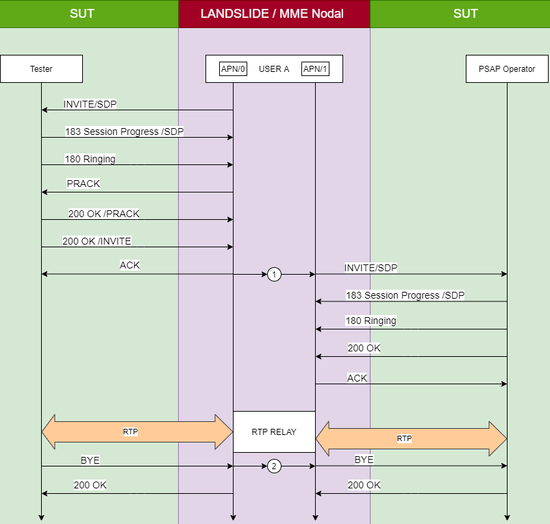
|
Mobility |
In MME Node test cases, the options available are None, Inter-MMME, Intra-MME, Inter-Tech, and Command Mode. The parameters descriptions are the same as those described above for MME Nodal test case. Tcl Parameter: MobilityType |
|
SGd Interface |
Select the SGd Interface to communicate with an SMS-IWMSC or SMS-GMSC. In the MME Node test case the SGd interface acts like the SGs interface – in that an SMS received over the NAS control plane (from an eNodeB) can be forwarded to the SMS-IWMSC over the SGd interface. SGd interface is a diameter interface that carries SMS messages between an MME and an SMS entity. An MME SGd Node tab also becomes active in the node definition section. Tcl Parameter: SgdInterfaceEn |
|
S102 Interface |
Select to enable configuring S102 tab. Tcl Parameter: S102InterfaceEn |
|
APN DNS Lookup |
Select to enable support for NAPTR Queries - Disabled if SGW/PGW Node Emulation is enabled. Tcl Parameter: ApnDnsEn |
|
ESMLC Node Emulation |
Select to enable Emulate ESMLC server for Location Services. Tcl Parameter: EsmlcServerEn |
| Slg Interface |
Available when LCS Support is enabled. Selecting SLg Interface provides the Slg interface tab in MME Node for EPC location services between GMLC and MME. Tcl Parameter: SlgEn |
| DC Interface |
Select to emulate the Dispatch Console (DC) Interface (part of LTE based Broadband Trunking Communication (B-TrunC). Select for support of D Interface between T-CN and DC which is based on SIP. Available only when S1-AP Version is = 10.5.0 or 10.6.0 or 11.1.0 and B-TrunC is enabled. Tcl Parameter: DcInterfaceEn |
| N26 Interface | The N26 interface provides a reference point between Access and Mobility Management function (AMF) and the Mobility Management Entity function (MME). The S11/N26 (GTPv2) interface becomes available for input. Enter AMF N26 SUT. Available on AMF Node and MME Node test cases. Tcl Parameter: N26En |
| SBc Interface |
Select for Warning Message Transmission procedure for EWTS test in MME Node. The CBC SUT and MME SBc Node become available for input. Use the HSS Node test case to generate ETWS message via SBc Interface and MME Node will forward the message to the S1 Interface. The S1-AP Warning Message Transmission Procedure is not available for input. Tcl Parameter: SbcIfEn |
T-ADS (Terminating Access Domain Selection) Information (MME Node and SGW Nodal)
|
Include Homogeneous IMS Voice over PS Sessions |
Available when the HSS Interface is enabled. If this option is selected, the HSS will include "Homogeneous-Support-of-IMS-Voice-Over-Ps-Sessions" AVP in Update-Location-Request (ULR) message to HSS. It is supported homogeneously in all TAs or RAs in the serving node. Tcl Parameter: ImsVoiceOverPsSessionsEn |
|
Include T-ADS Data Retrieval |
Available when the HSS Interface is enabled. If this option is selected, the HSS will include "Support-Features" AVP with bit 27 (T-ADS Data Retrieval) set in Update-Location-Request (ULR) message to HSS. Indicates the MMe/SGSN supports IMS Voice Over PS Sessions Data Retrieval. When receiving "Insert-Subscriber-Data-Request (IDR") from HSS with" IDR-Flags" AVP bit 1 (T-ADS Data Request) set, the HSS shall include "IMS-Voice-Over-PS-Sessions-Supported" AVP, "Rat-Type" AVP, and "Last-UE-Activity-Time" AVP in Insert-Subscriber-Data-Answer (IDA) message response. Tcl Parameter: TadsDataRetrievalEn |
|
SGs Interface |
SGs interface between MSC and MME. Available in MSC Nodal and MSC Node test cases. Tcl Parameter: MscInterface |
|
Gs Interface |
Select to enable interface between SGSN and the MSc (VLR). Uses BSSAP+ protocol. The interface allows paging and station availability when it performs data transfer. Available in MSC Nodal and MSC Node test cases. |
|
Iu-CS |
Enable the Voice over Iuh (Iu-CS) interface between RNC and MSC. When enabled, Number of MMEs is not available. Available in MSC Node test case. |
|
SGd |
SGd interface between MSC and MME. SGd interface is a diameter interface that carries SMS messages between an MME and an SMS entity. The SMS entity involved depends on the direction of the SMS. When an SMS message is being sent to a mobile subscriber via the SGd interface, a SMS-GMSC sends a Diameter MT-Forward Short Message request (TFR) to the MME. Reference : 3GPP TS 29.338. SGd is mutually exclusive with Gs and/or Iu-CS but can be enabled with SGs. Available in MSC Node test case. Tcl Parameter: SgdEn |
|
Mobility Support |
Select Intra-MSC for the Target Iu-CS interface to become available. Available in MSC Node test case. Options: None or Intra-MSC Tcl Parameter: MobilityType |
|
Validate IMEIs and IMSIs |
Available when Iu-CS is enabled. Enable to validate IMEIs and IMSIs. Available in MSC Node test case. Tcl Parameter: ValidateImeiImsiEn |
|
UMTS Version |
Available when Iu-CS is enabled. Select UMTS version. Options = 4,6,7,8. Default = 4. Available in MSC Node test case. Tcl Parameter: UmtsVersion |
|
Intra-HNB GW |
Available when Mobility Support Intra-MSC is enabled. When enabled, Target RNC SUT in Network Devices is not available. Available in MSC Node test case. Tcl Parameter: IntraHnbGwEn |
|
Short Message Service |
When enabled, the SMS becomes available for input on the SGs interface between MSC and MME. Available in MSC Nodal test case. Tcl Parameter: SmsEn |
Non 3GPP Access GW Node
| Emulator Mode N3IWF TWIF AGF |
Select either Non-3GPP Interworking function (N3IWF) or Trusted WLAN Interworking Function (TWIF) or AGF (Access Gateway Function), emulator mode. N3IWF provides the N2 (NGAP) , N3/N9 (GTPU Tab) and NWu (NWu IPSec) interfaces and N3IWF Node. See below. TWIF provides the NAS-5G (NAS-5G SM , MM), AAA (RADIUS), AP/SSID, GRE, DHCP Relay Agent interfaces and TWIF Node, DHCP Relay Agent Node. AGF provides the PPP, N2 (NGAP) and N3/N9 (GTPU Tab) interfaces and AGF Node. 5G System Architecture: Reference : TS 23.501, 23.502, 24.502
AGF :
|
| N2 to AMF | The N2 interface to AMF is always enabled. AMF N2 Node SUT and N2 to AMF Node are available for input. For Non-3GPP InterWorking to route messages outside of 5G RAN.
Tcl Parameter: N2ToAmfEn |
| N3 to UPF | The N3/N9 interface to UPF is always enabled. UPF N3 Node SUT and N3 to UPF Node are available for input. For Non-3GPP InterWorking to route messages outside of 5G RAN. Tcl Parameter: N3ToUpfEn |

Network Host Testing
|
Client Transport
|
Select the Transport protocol as IP/Ethernet or IP/PPPoE.
Depending on your selection the following options are available for configuration on the Mobile Subscriber pane: Physical Interface, Number of Nodes, Starting IP Address, Mac Address, Default Routing address, Next Hop Address, and Outbound Traffic Port. |
| Dual Stack |
Use the Dual Stack checkbox to enable the Network Host to operate concurrent IPv4 and IPv6 stacks. This displays the IPv4 and IPv6 nodes that must be configured. Define the IPv4/IPv6 stacks on the Network Host Node pane. Not available when Client Transport is IP/PPPoE. |
| Rx Interface |
Select Rx Interface to define the Rx interface between the PCRF and the Network Host. See also AF Node. The Rx Interface is available only when you your system is licensed for PCRF function. See the parameter to be configured on the Mobile Subscriber pane when you select Rx Interface. |
| Data IPSec |
Select to use IPSec to encrypt Data Traffic. Define IPSec parameters on the Data IPSec tab. |
OFCS Nodal Testing
|
Affinity Mode |
Select Affinity Mode to turn on performance improvement of Diameter Applications. Significant performance impact can be achieved with Affinity Mode, especially, when running multiple test cases on the same process. A higher activation rate/throughput can be expected. 5 test cases are optimum as all cores will be used per one process on the C100 S2. Other systems may have a different number of cores per process and the recommended number of test cases should be adjusted accordingly.
|
|
|
Node Functionality - PGW SGW |
In OFCS Nodal Testing, select PGW and/or SGW to simulate diameter accounting request via the Rf Interface to OFCS Node. Tcl Parameter: PgwNodeEn Tcl Parameter: SgwNodeEn |
OFCS Node Testing
|
Indicates the 3GPP LTE Spec Release version. Select the as required: Option: R10, R11 Default: R11
|
||
|
Select Affinity Mode to turn on performance improvement of Diameter Applications. Significant performance impact can be achieved with Affinity Mode, especially, when running multiple test cases on the same process. A higher activation rate/throughput can be expected. 5 test cases are optimum as all cores will be used per one process on the C100 S2. Other systems may have a different number of cores per process and the recommended number of test cases should be adjusted accordingly.
|
||
|
Diameter IPSec |
In OFCS Node Testing, use the Diameter IPSec checkbox to encrypt traffic between the OFCS Node and PDN Gw and/or Srv GW SUTs. Define the IKE settings on the IPSec tab. Tcl Parameter: DiaSrvIpSecEn
|
|
|
Select Multiple SUT Types to report separate statistics SGW and PGW. Separate statistics helps monitor PGW and SGW individually within the same test session. For example, per Rating Group monitoring, available for PGW only, is more helpful than per Bearer for PGW monitoring. Tcl Parameter: MultipleNodesEn |
||
|
Use Secondary OFCS Node to allow definition of both the Primary and Secondary Server Nodes to simulate Communication Loss Failover. See also OFCS Node. This is part of the Command Mode License feature. Tcl Parameter: SecondaryOfcsEn |
||
|
In OFCS Node testing, select Enabled to indicate Command Mode selection or select Sequencer. By default the Command Mode selection is Off. Select Command Mode Enabled to indicate that the test runs/executes in the Command Mode, where you can configure for Failover Recovery. |
|
|
Available when Secondary OFCS Node is enabled. When the Node Configuration supports primary and secondary servers or proxies, you can enable or disable failover support. Transport layer failure on the primary node can be simulated at a time that you define. The node notifies the client whether failover is supported or not with the CC-Session-Failover AVP Options: Not Supported or Supported Default: Supported Tcl Parameter: DiaSrvCcFailover |
||
Simulate Failover |
Use the drop-down list to enable failure simulation. Options: No , Communication Loss, Transport Loss Default: No Tcl Parameter: DiaSrvCcFailoverType |
|
|
|
Indicates the length for time for which the failover simulation process is active. After the specified time expires, the failover simulation process stops. Range: 0 to 100000 Default: 1000 Tcl Parameter: DiaSrvCcFailoverDuration |
|
|
Use the drop-down list to select the simulated failure trigger. Options:
Default: Before Any Sessions Established X: Indicates either the number of Sessions or number of seconds depending on your selection of Start Failover. The parameter is available when you select Secondary OFCS Node, Simulate Failover is not No and Start Failover is not Before Any Sessions Established. Range is 1 - 400000 Default: 1 Tcl Parameter: DiaSrvCcFailoverDelay Tcl Parameter: DiaSrvCcFailoverDelay
|
OCS Node Testing
|
Indicates the 3GPP LTE Spec Release version. Select the as required: Option: R9, R10, R11 Default: R11 Type of AVP included in the RAR message depends on the LTE Release version you select. See OCS App tab. |
|||
|
Select Affinity Mode to turn on performance improvement of Diameter Applications. Significant performance impact can be achieved with Affinity Mode, especially, when running multiple test cases on the same process. A higher activation rate/throughput can be expected. 5 test cases are optimum as all cores will be used per one process on the C100 S2. Other systems may have a different number of cores per process and the recommended number of test cases should be adjusted accordingly.
|
|||
|
Use the drop-down list to force the OCS node to send Re-Auth-Requests to the client for all active CC sessions. The client must respond with a Re-Auth-Answer and follow up with an update CCR for that CC session. You can define the starting time and transmission rate for the RAR messages, and choose whether the server node will respond in a positive or negative manner. Options:
Default: None |
|||
|
Re-Auth Rate |
The rate at which the test attempts to deactivate any active sessions with an ASR message when the test case is stopped. Range: 1 — Variable1 Default: 1 |
||
|
Start Re-Auth |
The number of seconds the node will wait, after all CC sessions are established, before beginning to transmit Re-Auth-Requests. Range: 10 — 65535 Default: 10 1 Maximum rates, number of sessions, and number of emulated nodes vary depending on the test application and the test system's licensed capacity. |
||
|
Secondary Proxy |
Use the Primary Proxy and Secondary Proxy checkboxes to indicate whether proxies will be emulated.
When you select Primary and Secondary proxy servers, Failover support (simulate Transport Loss failover) is available and the settings for the secondary server emulator are enabled.
|
||
|
Use Secondary OCS Node to allow definition of both the Primary and Secondary Server Nodes to simulate Communication Loss Failover. See also OCS Node. |
|||
|
In OCS Node Testing, use the Diameter IPSec checkbox to encrypt traffic between the OCS Node and PDN GW SUT. Define the IKE settings on the IPSec tab. Tcl Parameter: DiaSrvIpSecEn
|
|||
|
The Sy Interface between OCS Node and PCRF supports the Spending-Status-Notification-Request/Answer (SNR/SNA) message, and allows you to:
Tcl Parameter: DiaSrvSyEn |
|||
|
Select to enable Sy link with Ro interface. Tcl Parameter: DiaSrvSyLinkedToRoEn |
|||
|
In OCS Node testing, select Enabled to indicate Command Mode selection or select Sequencer. By default the Command Mode selection is Off. Select Command Mode Enabled to indicate that the test runs/executes in the Command Mode, where all Rating Group IDs and Service Ids associated with Multiple Services Credit Control are inactive and you manually configure values using the on-demand Command interface. |
PCRF Testing
| LTE Spec Version |
Select the required LTE Spec Version from the dropdown list. Options: 8.4.0, 8.5.0, 8.6.0, 8.7.0, 8.8.0, 9.4.0, 9.5.0, 9.6.0, 9.7.0, 9.8.0, 9.9.0, 10.6.0, 10.7.0, 10.8.0, 11.4.0, 11.6.0, 12.X.0 (Node only) Tcl Parameter: LteVersion
|
|
| Affinity Mode |
Select Affinity Mode to turn on performance improvement of Diameter Applications. Significant performance impact can be achieved with Affinity Mode, especially, when running multiple test cases on the same process. A higher activation rate/throughput can be expected. 5 test cases are optimum as all cores will be used per one process on the C100 S2. Other systems may have a different number of cores per process and the recommended number of test cases should be adjusted accordingly.
|
|
| Roaming | Select to enable the S9 tab and configure Diameter and TCP parameters. Also enable AGW I/F | Gx to configure PCC Rules parameters. Allows you to test the S9 interface between the emulated H-PCRF and V-PCRF. (See also PCRF Testing). | |
| AGW I/F | Use the AGW I/F checkbox to define Ty Diameter, Gx, or R3 (Diameter) interface to the PCRF. See also AGW Node | |
| AF I/F |
Use the AF I/F checkbox to define the Tx and Rx interface to the PCRF. See also AF Node. AF/IF check box is available only when you select AGW I/F check box with Ty Diameter or GX radio buttons. In PCRF Node testing, when you select the AF I/F, the Session Stop From parameter becomes available. Select the server to stop the session from the dropdown list. Options for Session Stop From are AF Server and AGW Server. |
|
| BBERF I/F |
Use the BBERF I/F checkbox to define the Gxc interface between AGW and PCRF. When you select BBERF I/F checkbox, the AF I/F checkbox is disabled and if you have AGW I/F check box, the Gx radio button is automatically selected for you (Ty Diameter, Ty RADIUS, and R3 are disabled). See also BBERF Node. |
|
| OCS I/F | Use the OCS I/F checkbox to define the Sy interface between the OCS and PCRF. When Sy and Gx are enabled, the Sy session is initiated when the first Gx session of the subscriber is established with the PGW. The Sy session is initiated by the PCRF by sending SLR to OCS. | |
| Session Control | The session control parameters are available only when you select AGW I/F check box with Ty Diameter or GX and AF I/F checkbox with Tx or RX radio buttons. | |
| Session Start |
Select the node to start the session first from the drop-down list. Options: AF Start First or AGW Start First |
|
| Session Stop |
Select the node to stop the session from the drop-down list. Options: AF Stop First or AGW Stop First |
|
| Wait | Enter the number of seconds to wait for the Server to stop the AGW. | |
| LTE Mobility |
In PCRF Node testing, selecting LTE Mobility allows handling of the messages exchanged during Hand Off. Some LTE handover may need to update the PCRF rules in the same Gx/Gxc sessions and others cause the PCRF Gxc/Gx session establishment or termination.
Select Inter SGW or Intra PGW from the dropdown list.
Use the PCRF Terminates Source Session checkbox to terminate UE initiated or PCRF initiated session.
|
|
| Command Mode |
In PCRF Node testing, select Enabled to indicate Command Mode selection or select Sequencer. By default the Command Mode selection is Off. Select Command Mode Enabled to indicate that the test runs/executes in the Command Mode, where all timers associated with PCC rules are inactive and you manually install or remove configured rules using the on-demand Command interface. |
|
|
In PCRF Node testing, enabled when both Gx and Rx interfaces are enabled. Support for Network Location. Tcl Parameter: NetLocEn |
PDF Nodal Testing
PGW Testing
| Network Interface |
In PGW Node test case, the label displays as PMIPv6 Network Interface. Select S5/S8 interface to display GTPv2 and PMIPv6 protocols. Select S2a or S2b network interface to display GTPv2 and PMIPv6 protocol. Select PI-MIP interface to display only MIP protocol. Tcl Parameter: NtwkInterface Select the GTPv2 Protocol to enable S5/S8 interface or S2a or S2b with GTPv2 protocol layer between the emulated Serving gateway and the PDN GW SUT. Define GTPV2 settings on the GTPv2 Tab. |
|
| Select the PMIPv6 protocol to enable IPv4 or IPv6 transport between the UE, MAG and LMA via the S5/S8 or the S2a/S2b interface. Define PMIPv6 settings on the PMIPv6 Tab. | ||
|
For PMIPv6 with IPv4 transport, you must enter the PMIPv6 Destination Address for LMA SUT on the Network Devices tab. In PGW Node test case, When Mobility = None, you may select Protocol as either GTPv2 or PMIPv6.
In PGW Node test case, select VLAN and enter the ID. |
||
| NEMO Tunnel Mode | Enabled when NEMO Emulation is selected. Select PMIPv6 (under NEMO Interface) to enable a GTP-U Tunnel and use it to tunnel PMIPv6 Control Messaging. Use NEMO LMA (SUT). Default = Pi-MIP (Use NEMO HA SUT) or PMIPv6 (NEMO LMA (SUT). Available in PGW Nodal and SGW Nodal test cases. IN SGW Nodal, only PMIPv6 is supported. Tcl Parameter: NemoTunnelMode | |
| Serving Node | In PGW Nodal testing, use the dropdown list to emulate SGSN or MME as from the Serving Node. For mobility tests, the Serving Node selection is forced to MME. | |
| Handoff Type |
In PGW Nodal testing, Handoff type is available only when the Test Activity Session Loading with Mobility and SGW Relocation. When either of these two Test Activities is selected:
Options: S1, X2, TAU Default: S1 Tcl Parameter: HandoffType
|
|
| Initial Network |
Select the Initial Network from the dropdown list. Options = Source or Target Default = Source Tcl Parameter: InitiateType |
|
| Sxb Interface to UP |
Select for the Sxb Interface to the Control and User Plane function in a split PGW Architecture. The Sxb Interface with the PFCP (Packet Forwarding Control Protocol) tab becomes available for input. The Sxb Control GTP Node and Sxb Control Node become available. Sxb to UP becomes available in Network Devices SUT for input. Enter the: Sxb User Node SUT, Sxb User GTP Node SUT, PGW User Node SUT. Up to 10 SUTs are supported. GTPv2 Version must be > 8.0.0 and Mobility not Inter Technology. See TS 23.214 for Architecture enhancements for Control and User plane separation of EPC Nodes. See TS 29.244 for Interface specifications between the Control plane and User plane of EPC Nodes. Tcl Parameter: SxbToPgwUEn |
|
| Sxb Interface to CP |
Select for the Sxb Interface to the Control and User Plane function in a split PGW Architecture. The Sxb Interface with the PFCP (Packet Forwarding Control Protocol) tab becomes available for input. The Sxb User GTP Node and Sxb User Node become available. Sxb to CP becomes available in Network Devices SUT for input. Enter the: Sxb Control Node SUT. Up to 10 SUTs are supported.
See TS 23.214 for Architecture enhancements for Control and User plane separation of EPC Nodes. See TS 29.244 for Interface specifications between the Control plane and User plane of EPC Nodes. Tcl Parameter: SxbToPgwCEn |
|
| Mobility Target |
Available when test activity is = Session Loading With Mobility, Command Mode, SGW Relocation and Sequencer. Network Interface = Select S5/S8 or S2a or S2b interface to display GTPv2 and PMIPv6 protocols. (Use Target S5/S8 or Target S2a/S2b or Target PMIPV6 Interface ) Tcl Parameter: MobNtwkInterface Support for Inter-tech mobility across GTPv2, PMIPv6 and MIPv4 with inner NEMO sessions. |
|
| UE Initiates Dedicated Bearers |
In LTE testing the dedicated bearers can be established by either the UE or the PDN. Selecting the UE Initiates Dedicated Bearers, allows all the provisioned bearers be established by the UE. If not selected, the PDN will establish the dedicated bearers as needed based on the traffic activity and QOS.
|
|
| Perform Revocation on Stop |
Available in PGW Node TC when Mobility is None and Protocol is PMIPv6. Select to indicate revocation occurs on stop and then trigger that invokes revocation.
Tcl Parameter: PmipRevocationTrigger |
|
| Direct Tunnel |
Use Direct Tunnel to enable the PGW to by-pass the SGSN and establish a direct connection to the GTP User Plane. In PGW Node TC, Direct Tunnel is available Mobility is Inter-Technology, Protocol is GTPv2, and UMTS Version is 7. |
|
| Billing (PGW) |
In PGW Nodal test case, The Billing checkbox is enabled only when Network Interface = S5/S8 and Protocol = GTPV2. In PGW Node test case, The Billing checkbox is enabled only when Protocol = GTPV2. Select Billing and then Ga, RF or Ro:
|
|
| Gx Interface |
In PGE Node test case, select to include Gx interface configurations. Gx, S6b and SGi NAS interfaces are mutually exclusive. (An example usage: You may use to test MME Nodal with VoLTE (capacity and Mobility) on one side and then IMS Node, MME Node, SGW Node, PGW Node with Gx and PCRF Node on the network side.) |
|
| S6b Interface |
In PGW Node test case, select to include S6b interface configurations. Provide linkage between PGW and AAA (S6b). Gx, S6b and SGi NAS interfaces are mutually exclusive. Tcl Parameter : S6bIfEn |
|
|
Select to enable Network Location. Available when Gx Interface is selected. Tcl Parameter: NetLocEn |
||
| SGi NAS Interface |
In PGW Node test case, select to include the SGi NAS interface (RADIUS Tab). Provides support for Radius query for authentication. Gx, S6b and SGi NAS interfaces are mutually exclusive. Tcl Parameter : SgiNasIfEn |
|
| NEMO Emulation |
Select to enable NEMO (Network Mobility) emulation, where groups of routers and UEs attached move homogeneously (as a whole). NEMO Interface will be Enabled. The option is not available when test activity is Session Loading with Mobility or when you select SGW Relocation. Available in PGW and SGW Nodal test cases. Tcl Parameter: MipNemoEn |
|
| Pi-MIP IPSEC |
Select to enable Pi-MIP- MIP NEMO tab. The option is not available when test activity is Session Loading with Mobility or when you select SGW Relocation. |
|
| VoLTE |
Available when test Activity is Capacity (except when Network Interface = Pi-MIP), Command Mode or Sequencer. Select to test the IMS VoLTE feature which supports SIP and RTP-based Voice over in PGW Nodal test case. You are required to configure the following:
|
| PDP Type |
Use the radio buttons to select the Packet Data Protocol type that is requested by the SGSN nodes or supported by a GGSN node. The applicable parameters will be displayed on the IPv4/IPv6 or PPP tabs depending on your selection. Options: IPV4, IPV6, IPv4/IPv6, PPP Default: IPV4
|
PSAP Node Testing
| PSAP Node |
Public Safety Answering Point (PSAP) testing to generate and answer emergency calls.
The following interfaces are available for testing :
|
| SIP VoIP |
Automatically enabled. Select to test the IMS VoLTE feature which supports SIP and RTP-based Voice over in PSAP Node test case. You are required to configure the following:
|
| Le Interface |
PSAP uses this interface for querying intermediate/final location of mobile subscriber. The Le Client and Le Interfaces become available for input. Tcl Parameter : LeEn |
| E2 Interface |
Available in PSAP Node and LCS Node test cases - The E2 interface is located between GMLC and PSAP and is used for querying location using Emergency Service Protocol (ESP). The E2 Interface - ESP Tab and Mm Interface become available for input. Per reference docs : NENA-05-001 December 2003 (NENA Standard for the Implementation of the Wireless Emergency Service Protocol E2 Interface) and J-STD-036-A - Enhanced Wireless 9-1-1 Phase 2 Tcl Parameter : E2En |

RIC Node / RIC Nodal Test Cases
RAN Intelligent Controller (RIC) is a network function in the disaggregated ORAN architecture that is responsible for control and optimization of the O-RAN elements with the goal of optimizing overall O-RAN performance. This is achieved through applications called xApps and rApps onboarded onto the near-RT and non-RT RIC respectively. xApps and rApps are geared towards specific use cases which represent specific aspects of the O-RAN to be optimized. Examples include Traffic Steering, Energy Savings, QoE optimization, etc. xApps and rApps rely on AI/ML models to ingest network data and make predictions and recommendations to optimize network performance.
|
Mode Non-RT Near-RT |
Select to emulate Non-RT RIC Node (default) or Near-RT RIC Node over the A1 interface. Mutually exclusive with E2 Interface.
When Mode = Non-RT :
When Mode = Near-RT :
Specification reference :
|
|
A1 Interface Test A1EI |
Select for A1 Interface between Non-RT RIC and Near-RT RIC. Currently, it is always enabled. Select Test A1EI to test the Enrichment Information Service. For A1-EI service, Near-RT RIC is consumer and Non-RT RIC is producer. Tcl Parameter: A1En Tcl Parameter: A1EiEn |
| E2 Interface |
Select to emulate the E2 Interface in RIC Node. Available when Near-RT is enabled. Mutually exclusive with A1 Interface. The interface that is designed for communication between DU/CU and Near-Real Time RIC is called E2. When E2 is enabled, there are two interfaces that become available for input :
When Mode = Near-RT, select the E2 Interface :
RIC Nodal Test Configuration can emulate gNB-CU (O-CU-CP and O-CU-UP together) and gNB-DU (O-DU). gNB-CU E2 Node, gNB-DU E2 Node, Near-RT RIC E2 Node SUT, E2AP Measurements, E2SM Measurements
Spec Reference:
Tcl Parameter: E2En Tcl Parameter: E2CccEn |
| O1 Interface |
Select for O1 interface for non-RT RIC testing from emulated CUs and DUs as part of non-RT RIC Nodal and RIC Node. The O1 interface supports the management entities within the SMO framework and includes the O-RAN managed elements such as the operation and maintenance (OAM), related to function of multi-vendor including FCAPS (fault, configuration, accounting, performance management, security management), and software.
When Mode = Near-RT (RIC Node TC), select the O1 Interface :
RIC Nodal Test Configuration can emulate gNB-CU (O-CU-CP and O-CU-UP together) and gNB-DU (O-DU). gNB-CU O1 Node, gNB-DU O1 Node, Non-RT RIC O1 HTTP SUT, O1-NETCONF (Service, SSH, TCP), O1-HTTP (Http/2 Client, TLS, TCP ) become available for input. NETCONF Measurements and O1 Service Measurements.
The following procedures are supported:
Spec Reference :
Tcl Parameter: O1En |
|
Command Mode Sequencer |
Command Mode is be visible when Mode = "Non-RT" and A1 Interface is checked or when Mode = "Near-RT" and A1 Interface plus TestA1EI are checked. Sequencer is the only option visible and cannot be un-selected. Click the Command / Sequencer button on the RIC Node Emulator Configuration to execute : For A1P: Query Policy Type Identifiers, Query All Policy Identifiers, Query Policy Type, Create Policy, Update Single Policy, Query Single Policy, Query Policy Status, Delete Policy Commands. For A1EI: Query Type Identifiers, Query Type, Query Job Identifiers, Create Job, Query Job, Update Job, Delete Job, Query Job Status, Notify Job Status, Deliver Job Result Commands For E2 (RIC): RIC Subscription, RIC Subscription Delete, RIC Control Commands For O1: Create MOI, Modify MOI, Delete MOI, Read MOI, Lock Data Store, Unlock Data Store Commands Additional details in RIC Node Test Case. |

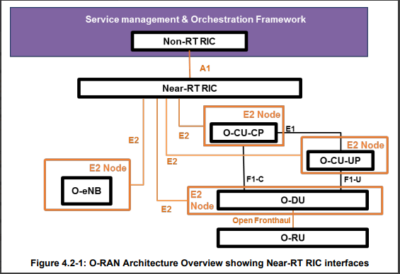

Security Gateway Node Test Case
| Site to Site VPN Support |
Site to Site VPN enabler Default = False Tcl Parameter: SitetoSiteEnabler |
||||||||||||||
| Unprotected Interface |
Select to add an Unsecured Gateway node. If enabled, the Security Gateway Node will forward decrypted packets towards the Network Host without any VLAN Id. See Security Gateway Node. Tcl Parameter: UnprotectedIfEn |
||||||||||||||
|
Number of Router Interfaces |
Select for Border Gateway Protocol (BGP).
BGP is a standardized exterior gateway protocol used to exchange routing and reachability information among different autonomous systems (ASes) on the internet. ISPs use BGP to "announce" or share information about the IP addresses and network routes they can reach. This is crucial for the proper functioning of the internet, as it allows routers across the internet to know how to forward traffic to reach destinations within an ISP's network. Each AS is assigned a unique identifier called an Autonomous System Number (ASN). When enabled, you can add up to 5 BGP Router Interfaces. Select Number of Router Interfaces. Range: 1 to 5. Default : 1 For each interface, add the parameters in Bgp Tab and BGP Router Node Measurements collected for BGP related processing are reported on the BGP Router Node tabs. Spec Reference :
Overview of BGP States -
Tcl Parameter: RoutingProtocolBgpEn Tcl Parameter: RoutingNumInterfaces |
||||||||||||||
| IPSec Peers - Number of Peers |
Number of IPSec Peers. Range from 1 to 300000 Default = 1 Note : The Tcl Parameter NumIpAddr can also be found on the Network Host Node. It is labeled as Number of Client IP Addresses which indicates the maximum number of client IP address supported by the node. Tcl Parameter: NumIpAddr |
||||||||||||||
| IPSec Peers - Number of APNs | Number of APNs - Only available if Site to Site VPN is NOT checked. Range from 1 to 11 Default = 1 Tcl Parameter: NumApns | ||||||||||||||

SCEF (Service Capability Exposure Function) Node Test Case - About SCEF Testing
| S6t | Select to enable the S6t Interface towards HSS.
S6t reference point is used for:
|
| T6a | Select to enable the T6a Interface towards MME.
T6a reference point is used for:
|
| T6b | Select to enable the T6b Interface towards SGSN.
T6b reference point is used for:
|
Service Based Nodal
| Test UDM (Nudm) |
Select to test the Unified Data Management function (Nudm). The SUT is UDM SBI, select to emulate AMF (N8), SMF (N10), AUSF (N13), SMSF (N21), and NEF (N52). NRF Interface is optional to be emulated. Tcl Parameter: TestUdmEn
|
||||||||||||||||||||||||
| Test AUSF (Nausf) |
Select to test the Authentication Server Function (Nausf). The SUT is AUSF SBI, select From AMF (N12), or Emulate UDM (N13). NRF Interface is optional to be emulated. Tcl Parameter: TestAusfEn
|
||||||||||||||||||||||||
| Test PCF (Npcf) |
Select to test the Policy Control Function (Npcf). The SUT is PCF SBI, select From AMF (N15), or From SMF (N7). NRF Interface is optional to be emulated. Tcl Parameter: TestPcfEn
|
||||||||||||||||||||||||
| Test CHF (Nchf) |
Select to test the Charging Function (Nchf). The SUT is CHF SBI, select From SMF (N40), From PCF (N28) or From SMSF. NRF Interface is optional to be emulated. Tcl Parameter: TestChfEn
|
||||||||||||||||||||||||
| Test NSSF (Nnssf) |
Select to test the Network Slice Selection Function (NSSF). The SUT is NSSF SBI, select From AMF (N22). NRF Interface is optional to be emulated. Tcl Parameter: TestNssfEn
|
||||||||||||||||||||||||
| Test NEF (Nnef) |
Select to test the Network Exposure Function (Nnef). The SUT is NEF SBI, select to Emulate AMF (N51) and / or to Emulate SMF (N29). NRF Interface is optional to be emulated. Tcl Parameter: TestNefEn
|
||||||||||||||||||||||||
| Test LMF (Nlmf) |
Select to test the Location Management (Nlmf). The SUT is LMF SBI, select From AMF (NLs). NRF Interface is optional to be emulated. Tcl Parameter: TestLmfEn
|
||||||||||||||||||||||||
| Test SLF (Nudr) |
Select to test the Subscription Location Function (Nudr). The SUT is SLF SBI, select From NRF. NRF Interface is optional to be emulated. Indirect Communication is disabled if Test SLF is enabled. Tcl Parameter: TestSlfEn
|
||||||||||||||||||||||||
| Test SMSF (Nsmsf) |
Select to test the Short Message Service function (SMSF). The SUT is SMSF SBI, select From AMF (N20). NRF Interface is optional to be emulated. Tcl Parameter: TestSmsfEn
|
||||||||||||||||||||||||
| Test UDR (Nudr) |
Select to test the Unified Data Repository (Nudr). Select From UDM (N35), From PCF (N36) or From NEF (N37). The SUT is UDR SBI, select From UDM (N35). NRF Interface is optional to be emulated. Tcl Parameter: TestUdrEn
|
||||||||||||||||||||||||
| Test BSF (Nbsf) |
Select to test the Binding Support Function (Nbsf). The SUT is BSF SBI, select From PCF or select From AF. NRF Interface is optional to be emulated. Services to be supported: Per 3GPP TS 29.521 version 15.4.0 section 4.2 Service Operations. BSF provides a PDU session binding functionality, which ensures that an AF request for a certain PDU Session reaches the relevant PCF holding the PDU Session information. This service: * Allows PCF consumers to register, update and remove the binding information; * our PCF Consumer update function, need to deregister first and then register with choose flag “update session binding” on message flow “Body Argument”. * Allows NF consumers to retrieve the binding information. We achieve PCF register, update, remove on BSF, AF discover PCF on BSF, and BSF Rx Proxy/Redirect between AF-PCF. Click to see Call flow. Tcl Parameter: TestBsfEn
|
||||||||||||||||||||||||
| Test 5G-EIR (N5g-eir) |
Select to test the Equipment Identity Register Services (5G-EIR). The SUT is EIR SBI, select From AMF (N17). N17 provides a Reference point between AMF and 5G-EIR. NRF Interface is optional to be emulated. Services to be supported: Per spec 3GPP TS 23.502 section 5.2.4 5G-EIR 5.2.4.2 N5g-eir_EquipmentIdentityCheck service 5.2.4.2.1 General
Additional details also available in 3GPP TS 29.511. 5G-EIR to check on PEI if its black listed as per 5.2.2.2.2 Procedure using CheckEquipmentIdentity Operation
Tcl Parameter: TestEirEn
|
||||||||||||||||||||||||
| Test H-SMF |
Select to test the N16 interface (V-SMF to H-SMF) for SEPP testing. Either Indirect Communication or Roaming Scenario with SEPP should be enabled when Test H-SMF is enabled. N16 testing is supported via SEPP and SCP. For V-SMF to discover the correct SMF via NRF, add the additional NF Discovery Query Parameter “target-plmn-list” for NRF client function. Spec reference: 3GPP TS 29.502 release 16.6.0 (2020-12). The SUT is SMF SBI, select From V-SMF (N16). NRF Interface is optional to be emulated.
Tcl Parameter: TestHsmfEn
|
||||||||||||||||||||||||
| Test NWDAF (Nnwdaf) |
Select to test the Network Data Analytics Function (NWDAF). Spec reference : 3GPP TS 29.520, 3GPP TS 29.510, 3GPP TS 23.288 (release 16.6.0 (2020-12)). NRF Interface should be enabled with NWDAF.
Tcl Parameter: TestNwdafEn
|
||||||||||||||||||||||||
| Test CBCF |
Select to test wireless emergency alert messages, where the system under test is CBCF and AMF is emulated by landslide. all the messages between CBCF and AMF. The messages for N50 interface are supported per 3GPP TS 23.041.
Tcl Parameter: TestCbcfEn |
||||||||||||||||||||||||
| NRF Interface | Select to test the NF Repository Function (NRF). The SUT is NRF SBI. Interface Nnrf Client.
When NRF interface is enabled, the SUT addresses is obtained by NF dynamic discovery procedure instead of static configuration. Thus, only NRF SBI SUT is editable for users to configure an address for NRF node, other SUT types (UDM SBI, AUSF SBI, PCF SBI) are only allowed to configure Number of SUTs. Currently, we support only one NRF node. For SB Nodal side, currently only UDM (as a NF service producer) needs to register itself (NF Type, NF services it provides) to the pre-configured NRF nodes via NF service registration procedure, other emulated NF s(AMF, SMF, AUSF, AF) act as NF service consumer role so needn’t to register on NRF. For SB Node side, all the emulated NF nodes (as NF service producer role) need to register themselves to the pre- configured NRF nodes via NF service registration procedure. Also available on AMF Node, SMF Nodal / SMF Node test cases. NRF Interface and UDM (N8) interface are mutually exclusive on SMF Nodal Test case. If Test UDM (Nudm) is checked:
If Test AUSF (Nausf) is checked:
If Test PCF (Npcf) is checked:
|
||||||||||||||||||||||||
| Test NRF (Nnrf) Emulate AMF AUSF BSF CHF NSSF PCF SMF SMSF UDM UDR UPF vNRF | Available when NRF Interface is enabled and all other interfaces are disabled.
AMF, AUSF, BSF, CHF, NSSF, PCF, SMF, SMSF, UDM, UDR, UPF and vNRF will be emulated in Service Based Nodal to support NRF Nodal test.
Tcl Parameter: TestNrfEn Emulate :
|
||||||||||||||||||||||||
| NF Register/Deregister Only |
Available when Test Activity = Session loading Test with "Test NRF" enabled. NF Register/Deregister Only is mutually exclusive with Message Flow. Select for Node Registration and De-registration without using Message Flows. When using Message Flow in SBI Nodal Session Loading when test NRF, Node Registration only happens during Test Case STARTING and Node De-Registration only happens during Test Case STOPPING. The Session loading mechanism was used to implement the NF nodes Register / De-Register actions. Using this approach, you can have an activation rate for NF nodes Reg, a deactivation rate for NF nodes De-reg, and ensure a constant rate like session loading. NOTE: The original Session loading was designed for session level message / command, this feature NF Register/Deregister Only is for node level messages, thus the new calculation logic for "Activation Time" is : Activation Time = "Total number of nodes" / "Activation Rate". "Total number of nodes" equals the SUM of the number (# of Nodes) ) of all the of nodes that are enabled on "Network Devices" as shown in the image below.
This NF Register/Deregister only checkbox is only available for selection in the Session loading Settings Tab when the "Test NRF" is checked; for other "Test XXX", it's not available. When enabled, Number of Subscribers, Starting SUPI, Starting GPSI, Emulate vNRF are not available for selection. Tcl Parameter: NfRegDeregOnlyEn |
||||||||||||||||||||||||
| Indirect Communication | Select for indirect communication via Service Communication Proxy (SCP) as specified in 3GPP TS 29.500 Section 6.10.3. In Indirect Communication, the NF Service consumer communicates with the target NF Service producer via a SCP. Landslide will emulate SCP in the Service Based Node test case. The SBI Interfaces have been enhanced to support SCP. Available in both Service Based Nodal (disabled if Test SLF (Nudr) is enabled) and Service Based Node (requires at least one emulation mode other than SCP or NRF (Nnrf), disabled if SLF (Nudr) is selected) test cases. Also available in SMF Nodal and SMF Node test cases. When enabled, interface SCP Client and SCP Sut become available for Input. Figure 4-2 gives more details about the Communication model for NF/NF services interaction. For more information, please refer to 3GPP 23.501. Landslide was enhanced to support model C, except that SCP will not be delegated to perform selection for specific NF Service instance from the NF Service Set and will not interact with NRF.
Figure 4-2 Communication model C for NF/NF services interaction. Model D - Indirect communication with delegated discovery: Consumers do not do any discovery or selection. The consumer adds any necessary discovery and selection parameters required to find a suitable producer to the service request. The SCP uses the request address and the discovery and selection parameters in the request message to route the request to a suitable producer instance. The SCP can perform discovery with an NRF and obtain a discovery result. The following figure depicts the communication models for Model D.
In SCP Client , select the 29.500 version to support :
Select the SCP version configuration in SCP Client tab to switch between these two different conveyances of NF discovery factors. By default, we only convey 3gpp-sbi-discovery-target-nf-type, 3gpp-sbi-discovery-requester-nf-type and 3gpp-sbi-discovery-service-names. We also provide the NF Discovery tab to append or overwrite NF discovery query parameters used in 3gpp-sbi-discovery-* headers.
Figure 4-3 illustrates the overall procedure for indirect communication without delegated discovery. In a successful discovery the NF service consumer gets the NF profile (s) matching the search criteria provided in the Nnrf_NFDiscovery_Request message. Then subsequence message flows between NF service consumer and NF service producer will be routed by SCP.
1. When the NF Service Consumer needs to send a Service Request and has stored results from the Discovery Procedure, the NF Service Consumer selects an appropriate NF Producer / NF Service Producer instance from the list of NF profiles provided by the NRF. The NF Service Consumer considers the NF and NF service parameters (e.g. TAI, S-NSSAI, locality, priority etc) in the NF profiles. The NF Service consumer requests service from the NF Service producer by sending a service request message to the NF service producer via the SCP. The address of a NF Service/NF producer instance may be unique per NF service/NF producer instance or may be shared by multiple NF service producers. i.e. the address used by the NF service consumer may point to multiple NF service/NF producer instances, or a single NF service producer instance. 2. If the NF Service consumer provides an End Point address pointing to multiple producer instances, the SCP performs selection of NF Service/NF Producer instance from the set of NF services that the address is pointing to. Otherwise the SCP uses the NF Service/NF producer Instance that the address points to. The SCP forwards the Service Request to selected NF Service/NF producer Instance. 3. The NF Service Producer responds via SCP. 4. SCP forwards the response. Note : We do not support Authorization header in Release 19.0. Indirect Communication is disabled when Test SLF (Nudr) is selected in the Service Based Nodal test case or when SLF (Nudr) is selected in the Service based Node test case. In Service Based Node, it requires at least one emulation mode other than SCP or NRF (Nnrf) to be selected. Tcl Parameter: IndirectCommEn |
||||||||||||||||||||||||
| Delegate NF Discovery And Selection |
Available when Indirect Communication is enabled. Select for support of Indirect Communication_NF discovery and selection per 3GPP Release 16 , Specification 29.500. When enabled, NF Discovery tab becomes available to enable the NF Discovery Query Parameters. When "Delegate NF Discovery And Selection" is checked, the target NF node configuration tab on "Network Devices" tab only allows the setting of "Number of SUTs" option, all other options are not available for input. (which is same like when "NRF Interface" is checked). Tcl Parameter: DelegateNfDscSelEn |
||||||||||||||||||||||||
| Generate TLS Key Log Files | See Generate TLS Key Log Files in Service Based Node Test Case. |


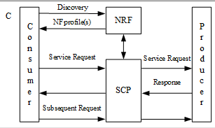


Service Based Node
| UDM (Nudm) |
Select to emulate UDM (Nudm)- Unified Data Management Function. Interface Nudm (Nudm NF Tab - NF Producer) becomes available for input. UDM SBI Node is available for input. Also available on HSS Node Emulator. See additional details here. Tcl Parameter: UdmEn |
||||||||||||||||
| AUSF (Nausf) To UDM (N13) |
The SUT is UDM SBI, select From AUSF (N13) - Authentication Server Function. Interface Nausf (NF Tab - NF Producer) becomes available for input. When To UDM (N13) is also enabled, AUSF-UDM (NF Tab - NF Consumer) become available for input. AUSF SBI Node is available for input. Tcl Parameter: AusfEn Tcl Parameter: N13En |
||||||||||||||||
| PCF (Npcf) |
Select to emulate PCF (Npcf)- Policy Control Function. Interface Npcf (Npcf NF Tab - NF Producer) becomes available for input. PCF SBI Node is available for input. When PCF (Npcf) is enabled, Visiting PCF becomes available to enable. When enabled, interface PCF-AMF (NF Tab - NF Consumer) becomes available for input. When PCF (Npcf) is enabled, To BSF becomes available to enable. When enabled, interface PCF-BSF (NF Tab - NF Consumer) becomes available for input. When PCF (Npcf) is enabled, To UDR (N36) becomes available to enable. When enabled, interface PCF-UDR (Pcf to Udr NF Tab ) becomes available for input. When PCF (Npcf) and Roaming Scenario with SEPP are enabled , To H-PCF (N24) becomes available to enable. When enabled, interface PCF-PCF (NF Tab - NF Consumer) becomes available for input. SUT is PCF (N24) SBI. N24 interface is for roaming scenarios, V-PCF will forward Npcf_UEPolicyControl Create/Update/Delete/Get request got from AMF to H-PCF, H-PCF sends Npcf_UEPolicyControl Create/Update/Delete/Get response to V-PCF, and then V-PCF forward these response to AMF. For UpdateNotify request, H-PCF sends Npcf_UEPolicyControl UpdateNotify to V-PCF, V-PCF sends response back to H-PCF, and V-PCF relays UpdateNotify to AMF, AMF sends response to V-PCF. Tcl Parameter: PcfEn Tcl Parameter: VisitPcfEn Tcl Parameter: NpcfNbsfEn Tcl Parameter: N36En Tcl Parameter: N24En |
||||||||||||||||
| NSSF (Nnssf) |
Select to emulate NSSF (Nnssf)- Network Slice Selection Function (NSSF). Interface Nnssf (Nnssf NF Tab - NF Producer) becomes available for input. NSSF SBI Node is available for input. Tcl Parameter: NssfEn |
||||||||||||||||
| CHF (Nchf) |
Select to emulate CHF (Nchf)- Charging Function (Nchf). Interface Nchf (Nchf NF Tab - NF Producer) becomes available for input. CHF SBI Node is available for input. Tcl Parameter: ChfEn |
||||||||||||||||
| NRF (Nnrf) |
Select to emulate NRF (Nnrf)- NF Repository Function. Interface Nnrf (NF Tab - NF Producer) becomes available for input. NRF SBI Node is available for input.
Tcl Parameter: NrfEn |
||||||||||||||||
| LMF (Nlmf) |
Select to emulate LMF (Nlmf)- Location Management Function. The SUT is AMF SBI. Interface Nlmf (NF Tab - NF Producer), LMF-AMF (NF Tab - NF Consumer) and LCS (Lpp and NRPPa Tab) become available for input. LMF SBI Node is available for input. Tcl Parameter: LmfEn |
||||||||||||||||
| NEF (Nnef) | Select to emulate NEF (Nnef)- Network Exposure Function. Interface Nnef (NF Tab - NF Producer) becomes available for input. NEF SBI Node is available for input.
|
||||||||||||||||
| GMLC (Ngmlc) |
Select to emulate GMLC (Ngmlc)- Gateway Mobile Location Center Function. The SUT is AMF SBI. Interface Ngmlc (NF Tab - NF Producer)and GMLC-AMF (Gmlc To Amf NF Tab - NF Consumer) become available for input. GMLC SBI Node is available for input. Tcl Parameter: GmlcEn |
||||||||||||||||
| SMSF (Nsmsf) |
Select to emulate SMSF (Nsmsf)- Short Message Service Function. The SUT is AMF SBI. Interface Nsmsf (NF Tab - NF Producer)and SMSF-AMF (NF Tab - NF Consumer), SMS Tab become available for input. SMSF SBI Node is available for input.
Tcl Parameter: SmsfEn |
||||||||||||||||
| SCP |
Select to emulate SCP- Service Communication Proxy. DNS is available for input. Interface SCP (SCP-NF Tab) and SCP-NF (SCP Tab) become available for input. SCP SBI Node is available for input. Tcl Parameter: ScpEn |
||||||||||||||||
| UDR (Nudr) |
Select to emulate UDR - Unified Data Repository. Nudr NF Producer (Nudr NF Tab) becomes available for input. UDR SBI Node is available for input. Reference Document : TS 29.505 v 15.4.0 Tcl Parameter: UdrEn |
||||||||||||||||
| SLF (Nudr) |
Select to emulate SLF- Subscription Locator Function. Nudr (SLF) NF Producer (Nudr NF Tab) become available for input. SLF SBI Node is available for input. Indirect Communication is disabled when SLF (Nudr) is enabled. Reference Document : TS 29.504 Section 5.3 Tcl Parameter: SlfEn |
||||||||||||||||
| BSF (Nbsf) |
Select to emulate BSF (Nbsf)- Binding Support Function (BSF). Interface Nbsf (NF Tab - NF Producer) becomes available for input. BSF SBI Node is available for input. Also available on DRA Node test case. Tcl Parameter: BsfEn |
||||||||||||||||
| CBCF |
Select to emulate CBCF - Cell Broadcast Center Function (CBCF). Interface Ncbcf (http2 Server) and CBCF-AMF (PWS, NGAP, NF Tab - NF Consumer) become available for input. CBCF SBI Node is available for input. Reference Document : 3GPP TS 23.041 Tcl Parameter: CbcfEn |
||||||||||||||||
| 5G-EIR (N5g-eir) |
Select to emulate 5G-EIR (Neir)- Equipment Identity Registry. Interface Neir (NF Tab - NF Producer) becomes available for input. 5G-EIR SBI Node is available for input. Tcl Parameter: EirEn |
||||||||||||||||
| CAPIF CF (Ncapifcf) |
Select to emulate the CAPIF (Common API Framework). It is responsible for mutual authentication, service and API discovery and invoking the API. CAPIF core function: This authenticates the API invoker, authorises invoker before using API services, publishes and stores API information along with charging and logs. API Publishing Function based on CAPIF-4 reference point. Interface Ncapifcf (NF Tab - NProducer) becomes available for input. CAPIF-3/4/5 SBI Node is available for input. Spec Reference : 29.222
Supported functions between NEF and CAPIF Core Function:
Tcl Parameter: CapifcfEn |
||||||||||||||||
| NWDAF (Nnwdaf) |
Select to emulate Network Data Analytics Function (NWDAF). Interface Nnwdaf (NF Tab - NF Producer) becomes available for input. NWDAF SBI Node is available for input. Spec reference : 3GPP TS 29.520, 3GPP TS 29.510, 3GPP TS 23.288 (release 16.6.0 (2020-12)) Tcl Parameter: NwdafEn |
||||||||||||||||
|
(Initiator / Responder) |
Select to emulate SEPP (Security and Edge Protection Proxy) on Service Based Node. Added support for both vSEPP and hSEPP emulation, using an option (Initiator / Responder) to indicate if the emulated SEPP initiates the N32-c handshake procedures or not. The N32 interface is used between the SEPPs of a VPLMN and a HPLMN in roaming scenarios. N32-c, a control plane interface between the SEPPs for performing initial handshake and negotiating the parameters to be applied for the actual N32 message forwarding. N32-f, a forwarding interface between the SEPPs which is used for forwarding the communication between the NF service consumer and the NF service producer after applying application level security protection.
N32-c Interface:
N32-f Interface:
Reference:
Interface pSEPP N32-c ( NF Tab - NF Producer), cSEPP N32-c ( NF Tab - NF Consumer), pSEPP N32-f (http2 Server), cSEPP N32-c (http2 Server), become available for input. SEPP N32-c SBI Node and SEPP N32-f SBI Node become available for input. The SUT is SEPP N32-c SBI and SUT is SEPP N32-f SBI. When SEPP is enabled, Interface SEPP-NF ( NF Tab - NF Consumer) and Interface SEPP ( NF Tab - NF Consumer) become available for input along with SEPP to NF SBI Node. Tcl Parameter: SeppEn Tcl Parameter: SeppRole |
||||||||||||||||
| SMF |
Select to emulate SMF (Nsmf)- Session Management Function (SMF) in support of N16 interface with SEPP. Interface Nsmf (Nsmf NF Tab) becomes available for input. SMF SBI Node is available for input. Tcl Parameter: SmfEn |
||||||||||||||||
| NRF Interface |
Select to test the NF Repository Function (NRF). The SUT is NRF SBI. Interface Nnrf Client. See additional details in Service Based Nodal - NRF Interface. For Node side, all the emulated NF nodes (as NF service producer role) need to register themselves to the pre- configured NRF nodes via NF service registration procedure. Also available on DRA Node and DRA Node test case. Tcl Parameter: NrfIntfEn |
||||||||||||||||
| Generate TLS Key Log Files |
Select to generate TLS Encryption Key Logs for Service Based Nodal and Node. Used in all HTTP/2 TLS connections. Tcl Parameter: TlsKeyLogFileEn |
||||||||||||||||
| Message Flow |
Select to enable the Message Flow Interface tab. Tcl Parameter: MessageFlowEn |
||||||||||||||||
| Roaming Scenario with SEPP |
Select for Roaming scenario with SEPP. Available in both Service Based Nodal and Service Based Node and AMF /SMF Node test cases. Available in AMF Node TC when Support Roaming and (N8 Interface or N12 Interface) are enabled. In Service Based Nodal testing, H-AMF is configurable only if "Roaming Scenario with SEPP" is checked, and Test UDM → From AMF (N8) or Test AUSF → From AMF (N12) is checked. It is mutually exclusive with Test NSSF → From AMF (N22). When enabled, interfaces Target Namf and Target AMF-UDM/Target AMF-AUSF become available. Target AMF SBI Node and SUT H-UDM/H-AUSF/H-NRF/H-SCP. In the roaming scenario with N8 or N12 interface enabled, the existing AMF node emulates the vAMF in visiting network, and registration procedure on visiting network is supported. When "H-AMF" is checked, both vAMF and hAMF are emulated, registration with mobility can be supported - registration on visiting network first, then move back to home network and Register. NOTE: When "H-AMF" is checked, there is a constraint for "Number of Subscribers": [Number of Subscribers] * 2 <= licensed session number. N32-f message forwarding procedures 6. N27 (vNRF-hNRF) 7. N21 (SMSF (Nsmsf to UDM (N21)) - Mutually exclusive with UDM, AUSF and N52 8. N52 (Nnef to UDM (N52)) If PRINS is negotiated as security mode on N32-f interface, the following testing scenarios are supported. 1.1.2.1. SUT: cSEPP - LS: NF (PLMN A) + pSEPP + cIPX + pIPX + NF(PLMN B)
1.1.2.2. SUT: pSEPP - LS: NF (PLMN A) + cSEPP + cIPX + pIPX + NF(PLMN B)
Based on 3GPP spec 33.501, when PRINS is used, the JWE profile shall only support cipher suites A128GCM and A256GCM, the JWS profile shall only support cipher suite ES256. Interface NF-SEPP ( NF Tab - NF Consumer) becomes available for input. The SUT is SEPP to NF SBI. Specification Reference:
Tcl Parameter: RoamSeppEn Tcl Parameter: hAmfEn |


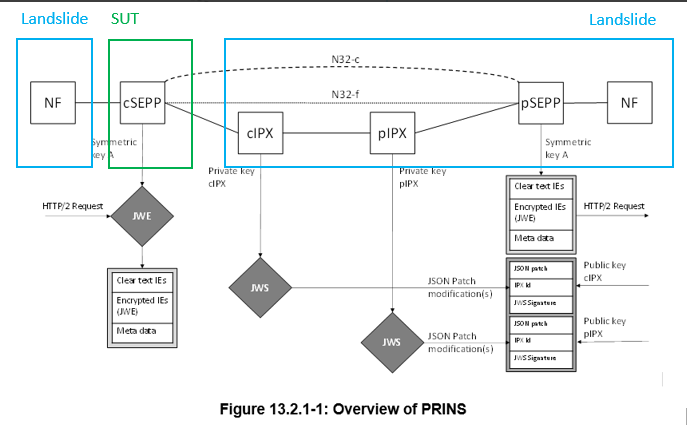

SGSN Node Test Case
| Mobility Support |
|
|
| Intra-HNB GW |
Available when Mobility support = Intra-SGSN. Tcl Parameter: IntraHnbGwEn |
|
| Perform Serving RNS Relocation Procedure |
The Perform Serving RNS Relocation Procedure is used only when doing a mobility test. When enabled, It will eliminate packet loss during handoff. For details on how it works please refer to 3GPP TS 23.060 v7.4.0. |
|
| Gn Interface |
In SGSN Node testing, selecting Gn Interface enables the GGSN SUT, SGSN's GTP Control Node, and the GTP User Node. The GGSN User SUT is optional and enabled when you select the Alternate User Address checkbox. See the SUTs enabled and connection established in SGSN Node testing. |
|
| Load Test PDP Context Only |
In SGSN Node TC, use the checkbox to set the session loading level (same as in UMTS Session Loading Test).
|
|
| Round Robin SGSN |
The Round Robin SGSN supports UMTS IuPS Flex testing with multiple SGSNs. When the Round Robin SGSN checkbox is disabled, all MNs are forced to attach to the first SGSN node (supports the IuFlex functionality).
|
|
| PGW Gn Interface |
PGW Gn Interface is available when UMTS version is 7. When you select PGW Gn Interface, the Gn interface tab and test configuration controls are available (similar to GGSN Gn Interface but are mutually exclusive). Type: True/False Default: False Tcl Parameter: PgwGnInterfaceEn |
|
| SGW S4 Interface |
SGW S4 Interface is available when UMTS version is 8. When you select SGW S4 Interface, S4 > GTPv2 interface tab is enabled for configuration. Type: True/False Default: False Tcl Parameter: SgwS4InterfaceEn |
|
| Validate IMEIs and IMSIs |
Select to indicate SGSN sends Attach Reject with wrong IMSI or IMEI. Type: True/False Default: False Tcl Parameter: ValidateImeiImsiEn
|
|
| Deactivate PDP after RAU |
Available when Mobility Support is Inter-SGSN or Intra-SGSN to support PDP Context Reactivation (deactivates contexts with cause code as reactivation required). You may also configure the deactivation interval and specify whether to perform one time deactivation process or continuous process. Tcl Parameter: DeactivatePdpAfterRauEn |
|
| Gr Interface |
Available when Protocol = UMTS and Mobility support = None. Defines the mapping and transport layers between SGSN and HSS/HLR Node. Tcl Parameter: GrInterfaceEn |
SGW Testing
|
Select the Initial Network from the dropdown list. This option is available when Test Activity is Inter Technology Mobility or Command Mode and HSGW Nodal Emulation is not selected. Initial Network indicates where the UE will initially attach / register. Select the Handoff Protocol below to indicate the "Target" network. For example: Initial Network = LTE , Handoff Protocol = GPRS (which is the Target). The UEs will initially attach / register to LTE then handoff to GPRS. The F2 Help key has been enhanced to indicate which network is the Target. Options: LTE, or one of the Target Handoff Protocol options (UMTS (IuPS over IP). UMTS (IuCS & IuPS over IP), GPRS, eHRPD, WiFi) Default: LTE
|
||||
|
In SGW Nodal testing, the Handoff Protocol option (UMTS (IuPS over IP). UMTS (IuCS & IuPS over IP), GPRS, eHRPD, WiFi) is available only when the Test Activity is Inter Technology Mobility.
|
||||
|
In SGW Nodal testing, different Handoff types are available depending on the Test Activity you select from the drop-down list. The Handoff Type determines signaling.
Options: TAU/RAU, INTER RAT Default: TAU/RAU Tcl Parameter: HandoffType TAU/RAU: Indicates that the handoff Routing Area Update procedure takes place when a UE registered with an MME selects a UTRAN or GERAN cell served by a Gn/Gp SGSN. In this case, the UE changes to a Routing Area that the UE has not yet registered with the network. INTER RAT: Indicates the Interoperation procedures takes place for Gn SGSNs and other EPS network elements— between SGSN and UE, between MME and eNodeB.
Options: S1, TAU/RAU Default: S1 Tcl Parameter: HandoffType
Options: X2, S1, TAU/RAU, Dual Connectivity Default: S1 Tcl Parameter: HandoffType Dual Connectivity: Indicates 4G to 5G dual connectivity - phase I. The SGW Nodal will handover between 4G eNodeB and 5G gNodeB. The gNodeB User Node becomes available in Network devices tab. The eNodeB User Node is not available for input.
Options: TAU/RAU, RNS Relocation Default: TAU/RAU Tcl Parameter: HandoffType
|
||||
|
Use the drop-down list to select the LTE release version that will be used in the test. Options: 7 or 8 Default: 7 Tcl Parameter: UmtsVersion
|
||||
| LTE Serving Node | In SGW Nodal testing, use the dropdown list to emulate SGSN or MME as from the Serving Node. For mobility tests, the Serving Node selection is forced to MME. | |||
|
|
The S5/S8 Protocol allows you to select PMIPv6 or GTPv2 protocols. During SGW Nodal testing, select:
During SGW Node testing, select:
Transport is available when PMIPv6 is selected. The Transport selection controls the PGW SUT lists on the Network Devices Tab:
|
|||
| S2a Protocol |
Available when the Test Activity is Inter-Technology Mobility and the Handoff Protocol = eHRPD. |
|||
| Sxa Interface to UP or Sxa+Sxb Interface to UP |
Select for the Sxa Interface to the Control and User Plane function in a split SGW Architecture. The Sxa Interface with the PFCP (Packet Forwarding Control Protocol) tab becomes available for input. The Sxa Control Node and Sxa Control GTP Node become available. The SGW User Node is disabled as well as the SGW S5 User node (if Separate S5 Interfaces is enabled). When PGW Node Emulation is enabled, the Sxa+Sxb Interface with the Sxa+Sxb Interface with the PFCP (Packet Forwarding Control Protocol) tab become available for input. Sxa to UP becomes available in Network Devices SUT for input. Enter the: Sxa User Node SUT, Sxa User GTP Node SUT, SGW User Node SUT. Up to 10 SUTs are supported. If Separate S5 Interfaces is enabled, the SGW S5 User Node SUT is available for input. Sxa+Sxb to UP becomes available in Network Devices SUT when PGW Node emulation is enabled along with Sxa Interface to UP. Enter the: Sxa+Sxb User Node SUT, Sxa+Sxb User GTP Node SUT, SGW User Node SUT. Up to 10 SUTs are supported. The Sxa+Sxb Control GTP Node and Sxa+Sxb Control Node become available. GTPv2 Version must be > 8.0.0. Available on SGW Node test case. See TS 23.214 for Architecture enhancements for Control and User plane separation of EPC Nodes. See TS 29.244 for Interface specifications between the Control plane and User plane of EPC Nodes. Tcl Parameter: SxaToSgwUEn |
|||
| Sxa Interface to CP or Sxa+Sxb Interface to CP |
Select for the Sxa Interface to the Control and User Plane function in a split SGW Architecture. The Sxa Interface with the PFCP (Packet Forwarding Control Protocol) tab becomes available for input. The Sxa User GTP Node and Sxa User Node become available. When PGW Node Emulation is enabled, the Sxa+Sxb Interface with the PFCP (Packet Forwarding Control Protocol) tab become available for input. The Sxa+Sxb User GTP Node and Sxa+Sxb User Node become available. Available on SGW Node test case. See TS 23.214 for Architecture enhancements for Control and User plane separation of EPC Nodes. See TS 29.244 for Interface specifications between the Control plane and User plane of EPC Nodes. Tcl Parameter: SxaToSgwCEn |
|||
|
Select PGW Node Emulation checkbox for control node availability (Bearer IP Address Pool is only available when emulation is on). The PGW Node Emulation checkbox is not available when Test Activity is Inter Technology Mobility or Command Mode. See also Network Devices tab for the SUTs and Node configuration enabled. During SGW Node testing, Bearer IP Address Pool is only available when you select PGW Node Emulation. The PGW Node Emulation checkbox is not available when you select Separate S5 Interface.
|
||||
| Data IPSec |
Select to use IPSec to encrypt Data Traffic. Define IPSec parameters on the Data IPSec tab. The Data IPSec option is not available if Default Bearers per Session > 1. |
|||
|
During SGW Node testing, Separate S5 Interface is available when S5/S8 Protocol is GTPv2 and when PGW Node Emulation checkbox is not selected. Select Separate S5 Interface to configure control and user node settings to test user plane tunneling and tunnel management between Serving GW and PGW. Tcl Parameter: SeparateS5InterfaceEn |
||||
|
During SGW Node testing, available when Separate S5 Interface is enabled. Select for same GTP-C TEID per MN on the S11 interface. "There shall be only one pair of TEID-C per UE over the S11 and S4 interfaces. The same tunnel is shared for the control messages related to the same UE operation." - Per 3GPP 29.274 Chapter 4.1 specification. Tcl Parameter: SameGtpcTeidS11En |
||||
|
In SGW Nodal testing, selecting the HSS Interface checkbox to enable the S6a interface. This parameter is not available when Test Activity is Inter Technology Mobility and UMTS Version is 7. The HSS SUT via the S6a interface enables transfer of subscription and authentication data for authenticating/authorizing user access to the evolved system (AAA interface) between HSS and MME. It also allows you to define the connection management settings for reliable transport over IP via the SCTP tab. On the S6a, and S6d tabs of SGW Nodal, disabled the Authentication fields for Secret Key and Operator Variant. In Location Information, disabled the Mobile Country Code and Mobile Network Code.
|
||||
| The PGW Gx Interface checkbox is available only when the PGW Node Emulation checkbox is selected in the SGW Nodal Test Case. Select the PGW Gx Interface checkbox to add a PCRF SUT (on the Network Devices tab) and the Gx interface tab. | ||||
|
In SGW Nodal test case, when you select EIR Interface and LTE Serving Node as MME S13 interface tab is available for configuration. When you select LTE Serving Node as SGSN and EIR Interface, then S13’ interface tab is available. By default, EIR Interface is not selected.
|
||||
|
In SGW Nodal testing, you can use the S1-U IPSec checkbox to encrypt traffic between the eNodeB and the Serving Gateway. See S1 IPSec tab for IPSec parameters. The Target S1-U IPSec checkbox is available when Test Activity is Session Loading with Mobility, Inter-MME, and Intra-MME. |
||||
| SGW Relocation |
In SGW Nodal test case, the SGW Relocation checkbox is available for Inter Technology Mobility and Inter-MME Mobility test activity. With these settings, you are also allowed to configure Target eNodeB User Node, Target SGSN Control Node and Target MME Control Node. When the Test Options are Inter Technology Mobility and you select SGW Relocation, the SGSN connects to Target SGW and Direct Tunnel may be selected. The GTPv2 tab displays Target Bearer Settings with handoff settings for ULI and QOS. SGW Relocation is not available when the Test Activity is Inter-SGSN Mobility and handoff type is Tau/Rau. |
|||
|
In SGW Nodal test case, the Billing is available only when PGW Node Emulation is selected. Select Billing and then Ga or Rf:
|
||||
| In SGW Node testing, UE Initiates Dedicated Bearers is available only when S5/S8 Protocol is GTPv2, PGW Node Emulation is selected, and the number of Dedicated Bearers is > 0. | ||||
|
During SGW Nodal testing, the Circuit Switched Fallback (CSFB) is available when Test Activity is:
If VoLTE is enabled, Circuit Switched Fallback is disabled and vice versa. Tcl Parameter: EnbCsfbEn
|
||||
|
During SGW Nodal Testing, DTM (Dual Transfer Mode) Support is available when Circuit Switched Fallback is selected and Handoff Protocol is GPRS (not available when Handoff Protocol is UMTS or eHRPD.). When the DTM Support is not selected the traffic data is not transferred after the session HO to GERAN. Tcl Parameter: CsfbDTMSupportEn |
||||
|
HSGW Node Emulation is available only if your system is licensed and when Test Activity is Command Mode. HSGW Node Emulation is selected by default when the S5/S8 Protocol is GTPv2 or PMIPv6. When you select HSGW Node Emulation, you are required to configure the PGW S2a SUT and Target HSGW Node on the Network Devices tab. Tcl Parameter: HsgwNodeEn |
||||
|
Available if you system has SGSN license and when Test Activity is Command Mode or Sequencer. When you select SGSN Node Emulation, the Handoff Protocol is either GPRS or UMTS and Circuit Switched Fallback is selected by default. Clearing Circuit Switch Fallback when SGSN Node Emulation is selected, greys DTM Support parameter.
Tcl Parameter: SgsnNodeEn When you select SGSN Node Emulation, the following options are available for selection.
In addition, PGW GN SUT and SGSN Control Node on Network Devices tab and Gn interface tab are is available for configuration. |
||||
|
The SWm Interface checkbox is enabled when ePDG Node Emulation is selected. This feature requires Command Mode and WiFi Offload Gateway licenses in order to be visible. The SWm interface is defined between the ePDG (Evolved Packet Data Gateway) and the 3GPP AAA server or between the ePDG and the 3GPP AAA Proxy for non-trusted non-3GPP access to EPS. The AAA- Diameter SUT and Target ePDG SWm Node on Network Devices tab and SWm interface tab are available for configuration.
Tcl Parameter: SwmIfEn |
||||
|
Available when test Activity is Capacity, Command Mode, Sequencer, Intra-MME Mobility, Inter-MME Mobility, Session Loading or Session Loading with Mobility when mobility type is Inter-MME or Intra-MME.
Select to test the IMS VoLTE feature which supports SIP and RTP-based Voice over in SGW Nodal test case. You are required to configure the following:
|
||||
|
Available if you have IMS license. When SRVCC is enabled, the I2 Interface becomes available. Tcl Parameter: SrvccEn SRVCC is available and when you select VoLTE. SRVCC is available only when Test Activity is Inter-Technology Mobility and
When PGW sends a Create Dedicated Bearer Request, it attaches a vSRVCC indicator for the Video Bearer (identified via avp_ims3gppPsToCsSessionContinuity_c). This AVP is added to RAR msg/Charging-Rule-Definition AVP while processing AAR msg from IMS Node; this AVP is also added when the received media type is VIDEO (AAR). During handover from 4G to 3G RTP/RTCP traffic for both voice and video is stopped and SIP call is internally released (terminated). IMS Node releases access call leg; the trigger is provided by PCRF Af application (Rx/RAR) that notifies bearer resources release. After Handoff back from 3G to 4G SIP traffic is resumed, that is, SIP call is re-established.
|
||||
|
Enable the I2 Interface - to/from the MSC to IMS for SIP portion of VoLTE calls after SRVCC Handover. |
||||
|
ePDG Node Emulation is available only if your system is licensed and when Test Activity is Command Mode or Sequencer. Select ePDG Node Emulation is selected by default when the S5/S8 Protocol is GTPv2 or PMIPv6. When you select ePDG Node Emulation, you are required to configure the PGW S2b SUT and Target ePDG Control and User Nodes on the Network Devices tab and GTPv2 tab on the S2b interface. When you select ePDG Node Emulation, S2b interface is available when S5/S8 Protocol is GTPv2 or PMIPv6. |
||||
|
Indicates support for IMS Emergency Session (Emergency PDN) and is available if your system is licensed. When enabled the Emergency PDN feature allows you to specify a subset of the UEs to be designated as emergency callers and may be identified by contiguous or non-contiguous IMSIs.
Type: True/False Default: False Tcl Parameters:
Range 0 - 10 Default: 0
Type: True/False Default: False Tcl Parameter: EmergencyAttachEn
Type: True/False Default: False Tcl Parameter: EmergencyAttachWoAuthEn |
||||
| AP Tunnel Type | In SGW Nodal test case, Tunnel Type options are: GRE L2 only. Available when Handoff Protocol = WiFi. | |||
|
Select to enable support for NAPTR Queries - Disabled when PGW Node Emulation is enabled. |
||||
|
Available when APN DNS Lookup is enabled and Default Bearers per Session is > 1. Select for SGW Anchoring with DNS Query. In this scenario, the subsequent NAPTR queries only ask for PGW and the previous SGW IP is used. Tcl Parameter: SgwAnchorEn |
||||
|
Available in SGW Node Emulator Configuration. Select for SGW Load balancing. Enter SGW Node Index. Range: 1 to 1000 Default: 1 Tcl Parameter: SgwLoadBalanceEn Tcl Parameter: SgwNodeIndex |
||||
|
Available when your system is licensed for Command Mode/Sequencer. Select to enable AP Tunnel Type and AP/SSID and GRE Interface/Tabs. If AP tunnel Type = None, UE-ePDG IPsec and VoLTE are enabled. |
||||
|
Select to enable Network Location. Available when PGW Gx Interface is selected. Tcl Parameter: NetLocEn |
||||
|
Select to enable LTE Relay UE support. This is a licensed option. Available when Test Activity = Capacity, Session Loading Test, Command Mode/Sequencer. S5/S8 protocol must = GTPv2, LTE Serving Node must = MME. LTE Relay Interface becomes available for configuration. See Relay UE section in SGW Nodal Test Case. Changes to the Test Case diagram: UE becomes Relay UE, eNodeB becomes Donor eNodeB, MME becomes Relay MME, SGW becomes Relay SGW and PGW becomes Relay PGW. Tcl Parameter: LteRelayUeEn |
||||
|
Select to disable recovery behavior of attempting to reattach UEs (via ODC). Used when UEs aren't in the right state or when session is idle. Available when Test Activity = Command Mode or Sequencer. Tcl Parameter: DisableReAttachOdc |
High Latency Communication- SGW
Functions for High latency communication may be used to handle mobile terminated (MT) communication with UEs being unreachable while using power saving functions e.g. UE Power Saving Mode or extended idle mode DRX depending on operator configuration. High Latency" refers to the initial response time before normal exchange of packets is established. That is, the time it takes before a UE has woken up from it's power saving state and responded to the initial downlink packet (s). The feature is described in 3GPP TS 23.682 and 3GPP TS 24.302.
|
Power Saving (T3324) |
Select to enable Power Saving (T3324). Range: 0 to 11660. Default: 20 Tcl Parameter: T3324PwrSavingValueEn Tcl Parameter: T3324PwrSavingValue |
||||||||||||||||||||||||||||||||||||||||||||||||||
|
T3412 Extended Value (s) |
This timer controls how frequently the tracking area update request is sent while in Power Saving Mode. Range: 2 to 35712000 Default: 40 Tcl Parameter: T3412ExValueEn Tcl Parameter: T3412ExValue |
||||||||||||||||||||||||||||||||||||||||||||||||||
|
eDRX Value |
Select to enable eDRX (extended idle Mode DRX). The eDRX Parameter consists of two bytes.
Default: "0x11". - See the breakdown below. Valid values are : 0x00 to (0xff or 0xFF) not case sensitive. If using the default value of "0x11" for WB-S1, per the tables below, the PTW (value of 1) = 2, 56 seconds and the eDRX (value or 1) = 10, 24 Seconds. If using the default value of "0x11" for NB-S1, per the tables below, the PTW (value of 1) = 5, 12 seconds and the eDRX (value or 1) = 20, 48 Seconds. (See Note 5 below)
The PTW Value can be applied to WB-S1 mode (WideBand-IoT) and to NB-S1 mode (NarrowBand-IoT).
Tcl Parameter: EDrxValueEn Tcl Parameter: EDrxValue |
||||||||||||||||||||||||||||||||||||||||||||||||||


Throttle Information - SGW Nodal
|
Select Throttle Data Notification Request to enable the SGW Node to support the handling of Data Notification Acknowledge messages with DL low priority traffic Throttling IE received from the SGW Nodal test case emulating the MME (TS 29.274 V15.6.0 Clause 7.2.11.2 and 12.3.3).
The Throttling Factor, in the DL low priority traffic Throttling IE which is included in the Downlink Data Notification Acknowledge messages, indicates the number percentage of downlink data messages that the SGW reduces. Range: 0 to 100 Default : 0
The Throttle Delay Time (s) indicates the length of time, in seconds, the SGW will reduce the number percentage of downlink data messages . Range: 1 to 300 Default : 1 Tcl Parameter: ThrottleDataNotifReqEn Tcl Parameter: ThrottlingFactor Tcl Parameter: ThrottleDelayLen |
SMF Nodal / Node
| Initial Network |
Select Initial Network. Available when Test Activity = Inter Technology Mobility in SMF Nodal test case. Initial Network indicates where the UE will initially start. Options: 5GS, LTE Tcl Variable: InitiateType |
| Handoff Protocol |
Select Handoff Protocol. Available when Test Activity = Inter Technology Mobility in SMF Nodal test case. Indicate Target network to handover from 5GS. Options : LTE (when Test Activity is “Inter Technology Mobility”), None (when Test Activity is “Sequencer” or “Command Mode”) SMF Nodal will create Gtp Bearers(SGW's role) as many as # of subscribers * # of PDUs and also create GTP Nodes. Each Gtp SGW bearer will be associated with UeSmSession per UE/PDU. S5 GTPv2 Tab , SGW Control Node and SGW User Node in Network Devices Tab become available for input. SMF+PGW SUT becomes available for input. Tcl Variable: HandoffProtocol |
| Handoff Type |
Select Handoff Type. Available when Test Activity = Intra-AMF Mobility, Inter-AMF or Inter Technology Mobility in SMF Nodal test case. gNB User Node and Target gNB User Node and SMF SUT are available for input and Target AMF SBI Node (when Test Activity = Inter-AMF Mobility) N2 and Mobility Registration Type are supported when Test Activity = Inter-AMF Mobility. N2 and Xn are supported when Test Activity = Intra-AMF Mobility. Handover and REG/TAU are supported when Test Activity = Inter Technology Mobility. Option : Xn, N2 , Mobility Registration Type , Handover , REG/TAU Tcl Variable: HandoffType |
| PDU Session Secondary Authentication | Select for Secondary Authentication during PDU Session Establishment. Click PDU Session Secondary Authentication to see details in AMF Section. |
| Data Traffic |
Enables the L3-7 Interface - Data Traffic tab. |
| NRF Interface |
Select to enable the Nnrf Client Interface. NF Tab (NF Consumer - Nnrf Client). NRF SBI SUT becomes available for input. NRF Interface and UDM (N8) interface are mutually exclusive on SMF Nodal Test case. Available on several other 5G test cases including AMF Node and Service Based Nodal/Node. Tcl Parameter: NrfIntfEn |
| Vo5G | Select to enable Voice over 5G testing. |
| UDM (N8) | Select for N8 (UDM) interface. See additional details in Serviced Based UDM (N8) Section. NRF Interface and UDM (N8) interface are mutually exclusive on SMF Nodal Test case. |
| Fireball |
Select to enable Fireball testing. |
| UPF Node Emulation |
Select for UPF Node Emulation. The N4 (PFCP ) and N6 (N6 Data Traffic) interfaces become available as well as UPF N3 Node, ,UPF N4 Node and UPF N4 GTP Node. SMF SBI SUT becomes available for input. Also available on the gNB CU SA Nodal test case. Tcl Parameter: UpfNodeEmulationEn |
| Support Mobility SBI Sessions |
Select whether to create two sets of all SBI Sessions per subscriber for “Inter-AMF Mobility” in Command Mode/Sequencer (Activate Connection, Release Connection, Xn Handover, N2 Handover , Reg Mobility).
Available for Command Mode/Sequencer with Handoff Protocol = LTE/None. Tcl Parameter: SuptMobSbiSessEn |
| UE-Requested PDU Session Modification |
Additional details in UE-Requested PDU Session Modification (in AMF Nodal section). |
| PGW-C Emulation |
Select for PGW-C Emulation testing. |
|
Traffic Steering |
The SUT is PCF SBI, select N7 Interface from SMF (Session Management Function) to PCF (Policy Control Function) . Interface Nsmf (NF Tab - NF Producer) and SMF-PCF (Smf to Pcf NF Tab - NF Consumer) become available for input. SMF SBI Node is available for input. When N7 is enabled, the NAS - 5g SM DNN Pane the label "QoS Settings" changes to "Subscribed QoS Settings" with limited fields available for capture. When N7 is enabled, Disconnect Dedicated Bearers after Connected is not available for input. 5G side: Added N11/N7/N4 interworking in support of the following: 1.UE Requested PDU Session Establishment. Added support of NAS-SM/N11 triggered Npcf_SmPolicyControlCreate request as well as handling of SmPolicyDecision received in Npcf_SmPolicyControlCreate response from PCF. Handling of both session rule and PCC rule installation were added (See limitation 1). QoS flow binding was implemented per 29.513 sec 6.4. Handling of PCF assigned dynamic QFI was also supported. 2.UE Requested PDU Session Release. 3. IMS/PCF triggered PDU Session Modification in support of the VoNR or EPS fallback scenario. 4G side: Added S11/S5/S8/N7/N4 interworking in support of the following: 1.UE Requested PDN Connectivity. Added support of NAS-ESM/S11/S5/S8 triggered Npcf_SmPolicyControlCreate request as well as handling of SmPolicyDecision received in Npcf_SmPolicyControlCreate response from PCF (See limitation 1). 2.UE Initiated PDN Disconnection. 3. IMS/PCF triggered dedicated bearer activation and deactivation in support of the VoLTE or EPS fallback scenario.
Limitations: When N7 Interface is enabled, Traffic Steering checkbox becomes available for selection. When enabled, the DNAI on Nas 5G Sm tab and the DNAI on N4 tab become available for input. Enable Traffic Steering for :
Limitations :
Tcl Parameter: N7En Tcl Parameter: TraSteEn |
| N10 Interface |
The SUT is UDM SBI, select N10 Interface - SMF (Session Management Function) to UDM (Unified Data Management Function). Interface Nsmf (NF Tab - NF Producer) and SMF-UDM (NF Tab - NF Consumer) become available for input. SMF SBI Node is available for input. Tcl Parameter: N10En |
|
Emulate H-SMF / V-SMF Support Interworking with EPS
|
The SUT is SMF SBI, select Emulate V-SMF ( visting SMF ) - Session Management Function. Interface Nsmf (NF Tab - NF Producer) and SMF-SMF (Smf To Smf NF Tab - NF Consumer ) become available for input. SMF SBI Node is available for input. Available on SMF Node test case only when N16 Interface is enabled and Emulate = H-SMF ( home SMF ). Interface Nsmf (NF Tab - NF Producer) become available for input. SMF SBI Node is available for input Select Support Interworking with EPS to indicate whether V-SMF supports the interworking with EPS which is required for 5gs/Eps handover in home routed roaming. Becomes available when Emulate is V-SMF. Select the GTPv2 Version on the Nsmf Interface. Added support for the following procedure in the home-routed roaming scenario: N16 Interface is disabled when PDU Session Secondary Authentication , or Support URLLC are selected. Limitations :
Tcl Parameter: N16Emulate Tcl Parameter: N16VSmfSuptIwWithEpsEn Tcl Parameter: N16En |
|
Off Enabled |
When Command Mode is enabled, a "Command" button becomes available under the N4 (PFCP ) tab. Select Enabled for SMF Node to initiate the following attacks based on the PFCP Session SEID(s) specified the user using Command Mode Test Activity - SMF Node Test Case.
Limitations:
|
| Multipart Message Options |
Select to input value instead of using the system default value (++Boundary) for the Boundary Delimiter. Also available in AMF Node test case. See TS 29.502 Annex B. HTTP Multipart Messages. Enter up to 70 characters. Valid set of characters: [a-z , A-Z, 0-9,:'()+_,-./=?] If ':' is used, the string must be in quotes. example: "abc:123" Select to Use Lowercase Header Field Name in Body Part. For example, if enabled, the name of "Content-Type" and "Content-Id" will be encoded as "content-type" and "content-id". Tcl Parameter: MptMsgBoundaryDelimEn Tcl Parameter: MptMsgBoundaryDelim Tcl Parameter: MptMsgLcHdrNameInBodyEn |
SMS Network
| SMS-SC |
The SMS-SC can be configured to:
Number of Recipients on Mobile Subscribers - SMS Terminating Pane defines the target subscribers for which an MT SMS message can be sent. Number of Originating Subscribers on Mobile Subscribers - SMS Originating Pane defines the target subscribers for which an MT SMS message can be sent. Tcl Parameter: SmsScMapCEn Tcl Parameter: SmsScMapEEn Tcl Parameter: SmsScT4En Tcl Parameter: SmsMode |
| SMS-HLR |
The SMS-HLR responds to requests received. it does not autonomously generate any MAP requests. The data in the SMS terminating pane on the SMS Network Test Configuration tab (mobile subscribers section), defines the number of subscribers and their associated identities that are recognized/supported by the HLR. When a map request is received, the HLR will validate that it recognizes the subscriber identified in the request and respond positively. If the HLR does not recognized the subscriber, it will respond with an error. Sms-Hlr is used to define the information sent from the SMS to the HLR from the SMS Network test case. Tcl Parameter: SmsHlrMapCEn Tcl Parameter: SmsHlrMapDEn Tcl Parameter: SmsMode |
| MSC |
The MSC can be configured to:
3GPP TS 29.338 (14.1.0) – this defines the Diameter based interfaces specific to SMS when used with SMS in MME architecture. This includes the S6c, SGd, and Gdd interfaces. The Gdd interface is not applicable. 3GPP TS 29.272 (15.6.0) defines the S6a interface. Number of Recipients on Mobile Subscribers - SMS Terminating Pane defines the target subscribers for which an MT SMS message can be received. Number of Originating Subscribers on Mobile Subscribers - SMS Originating Pane defines the target subscribers for which an MT SMS message can be received. Tcl Parameter: SmsMscMapDEn Tcl Parameter: SmsMscMapEEn Tcl Parameter: SmsMscSgdEn Tcl Parameter: SmsMscS6cEn Tcl Parameter: SmsMscSgsEn Tcl Parameter: SmsMode |
UE Emulator Data Node
|
UE Emulator Data Node
|
Adds the ability for Landslide to interoperate with an external Simnovus UE emulator for the purposes of sending/receiving simulated user data traffic. The Ue Emulator Data Node test case requires the common L3-7 tab to configure the DMFs. Modified to configure the number of PDUs per UE. The L3-7 tab modified to allow the DMFs to be assigned to a Default Bearer. For External Data testing, define a single ETH port and IP Address to serve as the External Data host. This is the IP Address is expected to be filled out in the Server's IP (in the User Plane pane) Address in DU Nodal Testing and also selected for the GTP Test Node in the UE Emulator Data Node Test Case. When user enabled the External Data, they will be required to select the "External Data Test Session" and it must contain a single "UE Emulator Data Node" Test Case. When the user started the DU Nodal test, if a External Data Test Session is selected that Test Session will be started first. Once it is confirmed started, the DU Nodal Test on the UE Emulator will be started. Interface with an external UE emulator. The emulator communicates to the Landslide TAS a REST API and a Websocket. The Simnovus system sends commands to the Landslide TAS as UEs are attached to the network an are ready for data. The TAS then sends new "c_run" commands to the UE Emulator Data Node test case to provision the UE IP Address with the following data:
Emulator Options For External Data testing, define a single ETH port and IP Address to serve as the External Data host. This is the IP Address that is expected to be filled out in the Remote UE Server Address in DU Nodal Testing and also selected for the GTP Test Node in the UE Emulator Data Node Test Case. Additional details in Common Node Parameters |
UE Node
|
UE Handset LTE U1 Modem |
UE Handset - select to perform tests (DNS, HTTP, etc) on a handset device (Android only). Must select a handset device by enabling Test UE/Select UE. UE table is populated via TS Admin - UE Tab. Follow instructions on UE Tab to get Handset connected and ready to test. Handset must have App installed before testing can begin.
LTE U1 Modem - Available on the E10 when running EDGE software. Enables support of real LTE SIM attached to an E10, Allows testing of L1-L3 over the LTE Uu Interface. Only one UE per module (up to four modules) is currently supported. OTA Nodes - Devices - becomes available for input (Assigned Interface from TS- Admin OTA Tab). Additional details when running tests using Sequencer (Settings available for LTE U1 Modem Type) - See On Demand Test Case Command for UE Node Test Case) This is a licensed feature.
Values of STATUS_OF_CLIENT parameter when UE Info level is 10 and UE info monitoring / reporting configuration is enabled:
Tcl Parameter: UeTestType |
|||||||||||||||||||||||||||||||||||||||||||||||||||||||||
| External Data |
Available when LTE U1 Modem is enabled. Enabled for Sequencer when Number of OTA UEs = 1. Sequencer will be blocked at OK if the UEs assigned Interface is not selecting a 5G Modem. External Data topic for additional information. Added support for Quectel 5G Modem to execute Sequencer Test On Demand Test Case Command for UE Node Test Case for ExecuteExtApps. |
|||||||||||||||||||||||||||||||||||||||||||||||||||||||||
|
VoLTE w/o SIP Authentication |
Available when LTE U1 Modem is enabled and Test Activity is not Sequencer. Select to test the IMS VoLTE feature which supports SIP and RTP-based Voice over in the UE Node test case. When Use SIM Server is not enabled, select VoLTE without SIP Authentication. Notes :
The VoLTE - Security Tab will be disabled and not available for input. You are required to configure the following:
|
|||||||||||||||||||||||||||||||||||||||||||||||||||||||||
|
Use SIM Server |
See additional detail in Use SIM Server in the Mobile Subscribers topic. |
|||||||||||||||||||||||||||||||||||||||||||||||||||||||||
|
Available when Test Activity = Mobility. This functionality supports the emulation of large numbers of Wi-Fi clients with either an over-the-air or a cabled interface toward an Access Point (AP) and Access Controller SUT. This functionality requires one of the following supported RF Client-emulation Wi-Fi Cards. RF Interface becomes available for capture. Tcl Parameter : WfoRfUeEn |
||||||||||||||||||||||||||||||||||||||||||||||||||||||||||
|
Select to support SWu IPSec with RF UEs enabled. Tcl Parameter : SwuIpsecEn |
||||||||||||||||||||||||||||||||||||||||||||||||||||||||||
|
Available when Type = UE Handset. Select Initial Network. Options = LTE or WIFI. Tcl Parameter : InitiateType |
||||||||||||||||||||||||||||||||||||||||||||||||||||||||||
|
Select UE Use SIM |
When you plug a real handset on the USB port, the Select UE table will get populated via TS Admin - UE Tab. Serial Number (SN) , Mobile Equipment Identifier (MEID) , Manufacturer, Product and USB Id are populated. Before you use the "Use SIM" feature, execute the Setup Script (Managing Test Server UE) and select Grab SIM Cards Info to write all available SIM cards to file on the handset. Then the TS must be Recycled for changes to be seen in Landslide. To add or remove a SIM card , re-run the handset setup script step. Select Use SIM to select a SIM from the available SIMs related to the selected handset list. The Select SIM panel includes : Active checkbox, Name of Sim, MDN and Provider. If no SIMs are reported by the UE, the SIM enabler will be forced deselected and shown as disabled/grey. See the Landslide Tcl API Object and Perform Function Reference or Using the RESTFul API. It contains reference information about the Landslide RESTFul API system. Refer to Swagger UI on Landslide Home Page, it contains the latest most accurate information for anything it covers. Go to the Parameter Class UeNode section for additional information. Tcl Parameter: Ue |
|||||||||||||||||||||||||||||||||||||||||||||||||||||||||
|
Select USB (Physical) connection. Only supported option at this time. Tcl Parameter: HandSetConnType |
||||||||||||||||||||||||||||||||||||||||||||||||||||||||||
| VisionWorks Inter-Carrier Intent-Of-Test for Messaging |
Select to indicate "INTER-CARRIER" INTENT_OF_TEST for the Modem SMS tests. UE_MSG and UE_TO_UE_MSG records for UuModem Interface. On Demand Test Case Command for UE Node Test Case) - SMS Send and SMS Receive. Tcl Parameter: MessageTestInterCarrierEn |
|||||||||||||||||||||||||||||||||||||||||||||||||||||||||
| Enable VoLTE Call POLQA |
Select for execute a POLQA VoLTE test for 4G Telit Modem. The checkbox is enabled for LTE U1 Modem when Sequencer is the test activity. When checked, the Test Data File selector panel labeled "POLQA Audio TDF (.wav)" is enabled. VoLTE Call Flows:
VoLTE POLQA MOS Measurement:
MO Side:
MT Side:
Please make sure to start MT side before MO side. User can achieve this by adding more delay for MO side in automation control. Notes:
Refer to the Use Case document for additional test setup. Tcl Parameter: PolqaTdfFileEn Tcl Parameter: PolqaTdfFile |
|||||||||||||||||||||||||||||||||||||||||||||||||||||||||
|
Additional details in topic UE Node App. |
||||||||||||||||||||||||||||||||||||||||||||||||||||||||||
|
Additional details in topic UE Node App. |
||||||||||||||||||||||||||||||||||||||||||||||||||||||||||
|
Additional details in topic UE Node App. |
||||||||||||||||||||||||||||||||||||||||||||||||||||||||||
|
Additional details in topic UE Node App. |
||||||||||||||||||||||||||||||||||||||||||||||||||||||||||
|
Additional details in topic UE Node App. |
||||||||||||||||||||||||||||||||||||||||||||||||||||||||||
|
Additional details in topic UE Node App. |
||||||||||||||||||||||||||||||||||||||||||||||||||||||||||
|
Additional details in topic UE Node App. |
||||||||||||||||||||||||||||||||||||||||||||||||||||||||||
|
Additional details in topic UE Node App. |
||||||||||||||||||||||||||||||||||||||||||||||||||||||||||
|
Additional details in topic UE Node App. |
||||||||||||||||||||||||||||||||||||||||||||||||||||||||||
|
Additional details in topic UE Node App. |
||||||||||||||||||||||||||||||||||||||||||||||||||||||||||
|
Additional details in topic UE Node App. |


UMTS Testing
In the UMTS test case, you can choose the type of protocols used, the release version, the test configuration, when PDP contexts should be activated, and the initiator for QOS updates.
| Protocol and Mobility/Handoff Protocol |
Use the drop-down lists to select the protocols and the type of interface (Iu-PS or Gb) that will be used in the test. The Mobility Protocol list is available when the Mobility or Session Loading With Mobility test activity is selected, and it allows you to select the configuration that will be used with the handoff SGSN. See About SGSN Testing for descriptions of the protocols used with each option. |
||
| Protocol and Mobility/Handoff Protocol Options: |
Default: UMTS (IuPS over IP) or GPRS depending on the application Tcl Parameter:
|
||
| UMTS Version |
Use the drop-down list to select the GPRS release version that will be used in the test. When you choose Release 6, the following parameters are enabled:
Options: 4, 6, 7, 8 Default: 4 Tcl Parameter: UmtsVersion |
||
| GGSN Node Emulation |
By default, the test case tests a SGSN SUT and a GGSN SUT. Use the checkbox to simulate the GGSN and change the test to an SGSN nodal configuration. When you use a GGSN node, the Gn tab defines the GGSN side of the Gn interface, the GGSN Control Node defines the simulator, and the address pool for PDP contexts is defined on the Mobile Subscriber pane. Must enable "Activate PDP Contexts upon GMM attach" or select Command Mode/Sequencer Test Activity for this field to become available.
|
||
| PGW Node Emulation |
PGW Node Emulation is available when UMTS version is 7. When you select PGW Node Emulation, the Gn interface tab and test configuration controls are available (similar to GGSN Node Emulation but are mutually exclusive). Must enable "Activate PDP Contexts upon GMM attach" for this field to become available. Type: True/False Default: False Tcl Parameter: PgwEmulationEn |
||
| SGW/PGW Node Emulation |
SGW/PGW Node Emulation is available when UMTS version is 8. When you select SGW/PGW Node Emulation, S4 > GTPv2 interface tab is enabled for configuration. Must enable "Activate PDP Contexts upon GMM attach" for this field to become available. Type: True/False Default: False Tcl Parameter: SgwPgwEmulationEn
|
||
| Activate PDP Contexts upon GMM Attach Deactivate PDP Contexts upon GMM Attach |
When you select the checkbox (default setting), the test will attempt to activate the number of PDP contexts defined on the Mobile Subscribers pane after an MN successfully attaches to the SGSN SUT. When you clear the checkbox, the test will only perform attaches and detaches with the SGSN. Deactivate PDP Contexts upon GMM Detach - when enabled the GUI will validate: Detach Rate must be <= PDP Deactivation Rate/PDP Contexts per UE PDP Contexts per UE = Number of Primary Contexts + (Number of Primary Contexts * Number of Secondary Contexts)
|
||
| Auto-Start Secondary Contexts |
By default, secondary PDP contexts are automatically activated after the associated primary context is activated. When the test includes secondary contexts, you can clear the Auto-Start Secondary Contexts checkbox and trigger activation of secondary contexts from within a DMF with event controls. Three default DMFs that trigger secondary context activation are provided in the Basic Library: |
||
| Direct Tunnel |
The Direct Tunnel feature is enabled when you select the UMTS version 7 or 8. Use the UMTS version 7 or 8 to enable the Direct Tunnel Feature and then select the Direct Tunnel- Primary RNC checkbox to use the RNC and GGSN to by-pass the SGSN and establish a direct connection to the GTP User Plane. When you select a Mobility or Session Loading With Mobility test activity, for UMTS protocol/mobility protocol, the Direct Tunnel- Target RNC becomes available. Select the Direct Tunnel- Target RNC checkbox to define the target RNC and GGSN to by-pass the SGSN and establish a direct connection to the GTP User Plane.
|
||
| Initiate Delete PDP Context |
When you select Initiate Delete PDP Context, the SGSN sends a Delete PDP Context Request to the GGSN, triggering the GGSN to release the context and tear down its tunnel with the SGSN. Upon completion, the GGSN replies with a Delete PDP Context Accept, allowing the SGSN to tear down its tunnel with the GGSN. |
||
| QOS Initiate |
When you select the QOS Update Test in an SGSN nodal test, you can use the radio buttons to select which device will initiate the PDP context update: the MN or the emulated GGSN. In an end-to-end test, MN is the only option. |
||
| Round Robin SGSN |
The Round Robin SGSN supports UMTS IuPS Flex testing with multiple SGSNs. When the Round Robin SGSN checkbox is disabled, all MNs are forced to attach to the first SGSN node (supports the IuFlex functionality).
|
||
| Billing |
In UMTS Nodal test case, the Billing checkbox is enabled only when the GGSN Emulation and Activate PDP Contexts upon GMM Attach checkboxes are selected. Select the Billing checkbox to define the Ga>GTP' billing data record information. |
||
| Log RNC Status |
In UMTS test case, select to ensure that the test run logs reports status of each RNC goes up or down. You may use the available log, for example, to reset some values on the SUT, ignore the associated set of ALARMS, and so on. The log reports
|
||
| Dual Connectivity |
Select to indicate if the MS supports Dual Connectivity of E-UTRAN with NR. It will be added to the MS Network Capability IE for Dual Connectivity NR in the Attach Request (per spec 3GPP TS 24.008 table 10.5.145). Available when Protocol = UMTS (IuPS over IP) and UMTS Version = 8.
|
UPF Nodal / UPF Node
| PGW-U Emulation |
PGW-U Emulation checkbox was added to UPF Node for 5G/4G mobility scenarios. Select PGW-U Emulation for UPF Node to internally allocate additional map space to accommodate multiple TEIDs (4G Uplink) per PFCP Session. Tcl Parameter: PgwUEmulationEn |
| N3 IPSec / Target N3 IPSec | Select for IPSec on the N3 / N3/N9 / Target N3 interfaces. Additional details here - N3 IPSec |
| NRF Interface |
Select to enable the UPF and Nnrf Client Interface. NF Tab (NF Consumer - Nnrf Client). Tcl Parameter: NrfIntfEN |
WiMax Testing
In addition to selecting a SUT with the WAC drop-down list, you can define the port used for the BS-WAC interface with WAC Port.
| EAP Authorization | If the SUT requires that MNs be authorized, you can use the checkbox to enable EAP-TTLS authentication. Click the EAP Settings... button to access the EAP parameters and configure the user credentials and digital certificate settings. Since EAP-TTLS is the only method used in WiMax testing, only those settings are displayed. |
| ISF | Select the check box to allow the MS to establish an Initial Service Flow (initial service flow) after attaching to the WAC. |
| Round Robin Configuration | Use the checkbox to enable round-robin configuration to distribute MSS. If you do not select the checkbox, the normal single WAC configuration is used to distribute MSS. |
Wifi Offload Gateway
Select the required options to perform Wifi Offload Gateway testing.
| Inter SSID/GW Mobility |
Select Inter SSID/GW Mobility to test mobility between SSIDs and include DHCP messaging.
Tcl Parameter : InterSsidMobilityEn |
||||
| Inter Access Point Mobility | Select Inter-AP Mobility to test mobility between the access points. The data messages from the UE go through a different Access Point and performs “seamless mobility”. Tcl Parameter : InterApMobilityEn | ||||
| Data Traffic Data IPSec |
Select to support IPSec tunnel between UE through the AP to the Wifi Offload Gateway. Selecting Data IPSec supports IPSec Tunnel irrespective of the Tunnel Type (GRE, CAPWAP, or None).
Configure L3-7 | Data IPSec tab. |
||||
| DHCP Relay Node Emulation |
Select to indicate that the DHCP Relay Agent forwards all the messages from DHCP server to the UE. In the 802.11 WLAN, AP is first hop of STA. The DHCP Relay Agent is an embedded function of AP. AP will analyze each message from STA. If the messages are DHCP message, it’ll invoke the DHCP relay function and forward them. All the messages from DHCP server are also handled by the DHCP Relay Agent and then forwarded to UE. DHCP Relay Node Emulation is not available when you select IP Address Type as Dual Stack on Mobile Subscriber pane or AP Tunnel Type = DS Lite. Tcl Parameter : ApDhcpRelayEn |
||||
| AP Tunnel Type |
Indicates the Tunnel Type between Access Point and Gateway: Options: GRE L2, CAPWAP, NONE, GRE L3, DS Lite, L2TPv3
When Tunnel Type is CAPWAP, UE DHCP via GRE Tunnel is not available.
Tcl Parameter : TunnelType |
||||
| Hybrid Access |
Available when Tunnel Type is GRE L3 and is selected by default to configure the network for Hybrid Access. Configure DSL and LTE access information on the Hybrid tab, HG LTE Node and HG DSL Node, and HAAP (Hybrid Access Aggregation Point) SUT. Hybrid Access indicates the bundling of two or more access line over different technologies (e.g. DSL and LTE) to one (Internet) connection. Tcl Parameter : HybridAccessEn |
||||
|
Available when Tunnel Type is GRE L3. Select the Hybrid Access GRE L3 Protocol type. GRE protocol type is 0x0101 for Rev_2 and 0xB7EA for Rev_5. The Tunnel type used only 1 bit - bit 3 in Rev_2 but Rev_5 uses all 4 bits (0-3) LTE Protocol value was 0 (0000) for Rev_2 and 2 Rev_5 (0010) DSL Protocol value was 1 (1000) for Rev_2 and 1 for Rev_5 (0001)
Options: Rev2, Rev5 Default: Rev2 Tcl Parameter : GreL3ProtocolType |
|||||
| AP-WAN IPSec |
In Wifi offload Gateway Nodal, select to establish IPsec tunnel between AP and Security Gateway (SecGW).
|
||||
| RF UEs |
This functionality supports the emulation of large numbers of Wi-Fi clients with either an over-the-air or a cabled interface toward an Access Point (AP) and Access Controller SUT. This functionality requires one of the following supported RF Client-emulation Wi-Fi Cards. RF Interface becomes available for capture. Tcl Parameter : WfoRfUeEn |
||||
| RF AP Emulation |
This functionality will simulate a software AP. Each AP supports up to 200 clients. If Emulate DHCP Relay Node in Wifi Offload Test Case is enabled, then the Access point will act as a DHCP Relay Node. Specify the DHCP server in the DHCP Relay Agent Tab. AP RF Interface becomes available for capture. Tcl Parameter : WfoRfApEn |
||||
| SIP VoIP |
Enable Volte support . SIP VoIP tab will become available. |
||||
| Specify Mobile Subscriber APNs |
Available when AP Tunnel type is None and Data Ipsec is selected. Enables the Number of APNs checkbox. Used for the scenario where WOGW Nodal is working with EPC. Tcl Parameter : WfoMsApnsEn |
||||
| AP-WAN PPPoE |
Enables the PPP tab which is used to configure PPoE Client parameters. This is only available when AP Tunnel Type = GRE L2. Tcl Parameter : PppOeEn |
||||
| Failover Testing |
Checkbox is available only if CAPWAP license is present. Enabled when AP Tunnel Type = CAPWAP and licensed for CAPWAP. Used for CAPWAP failover testing, AP/SSID Tab - Update Failover Testing pane with IP Addresses. Tcl Parameter : FailoverTestEn |
||||
| Flex Offload |
Checkbox is available only if CAPWAP license is present. Enabled when AP Tunnel Type = CAPWAP and licensed for CAPWAP. Used for port based separation of control and traffic data. When enabled, Data Traffic from emulated AP will go over IP directly to Network Host, not in CAPWAP tunnel. Control Traffic still goes to controller inside CAPWAP Tunnel. Tcl Parameter : FlexOffloadEn |
||||
| MOBIKE |
Checkbox is available when Test Activity = Mobility, Data IPSec is enabled and AP Tunnel Type = NONE. Select for MOBIKE Protocol. If MOBIKE is selected, Inter Access Point Mobility and Specify Mobile Subscriber APNs are automatically checked. Dual-Stack cannot be selected. The UE Target Static Ipv4 or UE Target Static IPv6 must be filled and the source and target IP cannot overlap. Tcl Parameter : WfoDataMobikeEn |
||||
| E911 Location Load Test |
Select for E911 Load Testing emulating the same UE(s) is attached to a different location each time it makes an emergency call. Must enable SIP VoIP and Enable Emergency on SIP VoIP tab. When enabled, the E911 Location Load Test pane becomes available for input. The Phonebook tab becomes available and the Emergency phone number to emergency service URN translation pane is available for input. E-CSCF: The Emergency CSCF handles certain aspects of emergency sessions, e.g. routing of emergency requests to the correct emergency center or PSAP. Emergency Service Query Key (ESQK): A 10-digit North American Numbering Plan number used to identify a particular emergency call instance. It is used by the LRF as a key to look up for the location information and callback information associated with the emergency call instance and is also used by the PSAP to query location information from the LRF. Wireless E911 ESRD/ESRK Number: A 10-digit number used for the purpose of routing an E911 call to the appropriate Public Safety Answering Point (PSAP) when that call is originating from wireless equipment. The Emergency Services Routing Digit (ESRD) identifies the cell site and sector of the call origination in a wireless call scenario. The Emergency Services Routing Key (ESRK) uniquely identifies the call in a given cell site/sector and correlates data that is provided to a PSAP by different paths, such as the voice path and the Automatic Location Identification (ALI) data path. Both the ESRD and ESRK define a route to the proper PSAP. Location Retrieval Function (LRF): This functional entity handles the retrieval of location information for the UE including, where required, interim location information, initial location information and updated location information. Public Safety Answering Point (PSAP): A physical location, where emergency calls from the public are received. Tcl Parameter : WfoE911LoadTestEn E911 Location Load Test (pane) - AP Test Parameters Test Data File Test Data File - A TDF input file will be used. It contains the Access Type and AP IDs. See example. The access Type can be any of the following: IEEE_80211 = 0 IEEE_80211_A = 1 IEEE_80211_B = 2 IEEE_80211_G = 3 IEEE_80211_N = 4 Select the TDF Row Limit (range from 1 to 400,000 (default= 500). Example of TDF file: Each time UE make a call it picks a random entry from 0 to 399,000 and apply Access Type and AP ID from this entry into SIP P-ANI header.
Select Stop Test Case when TDF is Completed to stop the test case automatically after the final entry in the AP Test Parameters TDF file is used when testing E911 VoLTE Scenarios. Tcl Parameter : E911CgfFile Tcl Parameter : E911CfgFileRowLimit Tcl Parameter : E911StopTestCaseEn |
||||
| Data via GRE Tunnel |
Available in Wifi Offload Gateway Nodal when Flex Offload has been enabled and AP Tunnel Type = CPAWAP. Select to send data via GRE tunnel to the address configured in GRE Tunnel Endpoint Address: Enter a valid IPv4 or IPv6 address. Tcl Parameter : GreTunnelEn Tcl Parameter : EndpointAddr |
||||
|
Select to support SWu IPSec in the Wifi Offload Gateway Nodal and UE Node test cases with RF UEs enabled and not Session Loading Test Activity. Enter Valid IPv4 address in UE SWu IPv4 Address. Tcl Parameter : SwuIpsecEn |
|||||
| Dual DHCP Relay Agent Node |
In Wifi Offload Gateway Node test case, select to indicate supports for Dual Stack (UE DHCPv4 + UE DHCPv6). The two DHCP relay agent nodes forward the IPv4 and IPv6 DHCP messages individually. One is used for DHCPv4 messages forwarding, and the other is used for DHCPv6 messages forwarding. |
||||
|
In Wifi Offload Node test case, select Gn to GGSN to configure GTP parameters (GTP-U). Indicates the network side Gateway supports termination via Tunneled 3G (GGSN emulation over Gn). |
||||
|
In Wifi Offload Node test case, select S2b to PGW to test mobility support between eHRPD access and the PGW. Indicates the network side Gateway supports termination via Tunneled 4G (PGW with either GTPv2 S2a ). |
||||
|
In Wifi Offload Node test case, select S2b to PGW to test mobility support between ePDG and the Gateway. Indicates the network side Gateway supports termination via Tunneled 4G (PGW with either GTPv2 or PMIPv6 over S2 ). S2a/S2b Protocol is available when you select S2b to PGW.
|
|||||
| CoA Simulation |
In Wifi Offload Node testing, select the CoA Simulation check box to enable and define the CoA Simulation parameters (CoA Simulation) on the RADIUS tab. Tcl Parameter: RadCoaSimulationEn |
||||
| Disconnect Simulation |
In Wifi Offload Node testing, select the Disconnect Simulation checkbox to define the Deactivation Rate (session/sec) for the Mobile Subscribers. Tcl Parameter: RadDisconnEn |
||||
| Firmware Download Emulation Firmware Size |
In Wifi Offload Node test case, select for Firmware Download emulation (Per RFC 5415). This is only available for CAPWAP Tunnel Type. Enable and Enter the Firmware Size. Range: 0 to 65535 Default: 65535 Tcl Parameter: CapWapImgDownLoadEn Tcl Parameter: CapWapImgDataSize |
