DU Nodal Testing
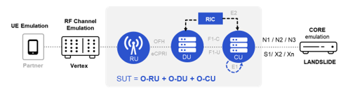
The DU sits between the CU and one or more RUs. The DU is a logical node hosting RLC/MAC/High-PHY layers based on a lower layer functional split. A single DU can manage many RUs. DUs can be virtualized and deployed on vendor-neutral COTS hardware. The DU can be tested in isolation, in wraparound testing mode. In this case, Landslide emulates all the network functions surrounding the DU, including RUs & UEs, Core network, eNBs/gNBs, neighboring CUs and RIC. The Core network emulation can be 5GC for SA mode.
Key Features
The Landslide DU Testing feature set includes the following capabilities:
• Single UI controls all functional blocks
• Standalone (SA) modes
• Emulation of UEs, CUs, RUs and 5GC and/or 4G EPC to surround the DU being tested
• Relevant interfaces 7.2x. F1-C, F1-U, E2, O1 are supported
• Control plane and user plane testing
• Functional, performance & capacity testing
• Support for intra-DU & inter-DU mobility scenarios
• High performance solution that can be scaled to multiple RUs, each RU with up to 256 emulated UEs
• Call modeling capabilities to shape test traffic as needed, for control and user planes
• Highly customizable, with ability to edit messages onsite as needed
• Automation through RESTful or Tcl API - Using the RESTFul API , Using the TCL API
Benefits
Landslide DU testing provides a flexible, scalable, high- performance solution for comprehensively testing the DU for compliance, functionality, performance & capacity. Additional details in About O-RAN O-DU Testing.
DU Nodal Test
Prior to setting up the DU Nodal test, follow the setup instructions in the Deployment Guide. It can be found on the Spirent Customer Service Center (CSC) https://support.spirent.com/SpirentCSC under the current Landslide release. Configure the address of the Simnovus UE Emulator for ORAN DU Nodal Tests using the Simnovator Administration window.
DU Nodal Test includes coverage for UE Emulators (Simnovus), Vertex Channel Simulator, CU/Core Test Session and External Data Test Session. DU Nodal provides the sequencing and synchronization of all of these sub components.
Reference document from Simnovus for UE Simulator - UE Simulator. User Manual version 3.3.0.
DU Nodal options are found under the Session Menu -
- Select Session > New DU Nodal Test from the Main menu to start a new DU nodal test.
- Select Session > Open DU Nodal Test from the Main menu - The Run button will be enabled if DU Nodal Test has been configured & saved.
- Select Session > Reconnect DU Nodal from the Main menu - Similar to Reconnect to active Test Session, the GUI will display list of currently running DU Nodal tests started by the user and if none are active, then it will display a dialog stating “No disconnected DU Nodal tests found for User: [username]”.
- Run/Stop DU Nodal - Once the test has been configured, click Run or Stop to execute the test or to stop it.
|
1. |
Select Session > New DU Nodal Test from the Main menu and enter data on the screens provided. DU nodal test case details provided below. The DU Nodal Templates library becomes available when you are properly licensed. It contains pre-defined Test Sessions, DMFs, TDFs and DU Nodal Tests that are available for use. |
| 3. |
Select Import to import/add an existing test case. Additional details in Adding a Test Case. |
| 4. | Click Save to create your test. Click Close to close the session without adding a test. |
Open / Reconnect DU Nodal Test
| 1. |
Select Session > Open DU Nodal Test from the Main menu - The Run button will be enabled if a DU Nodal test has been configured & saved, you cannot create and run ad-hoc DU Nodal tests. To create a new DU Nodal test, select New DU Nodal Test from the Main menu. Once DU Nodal has been started Abort / Stop / Run / Import / Save / Close buttons will be enabled. The current status of the active DU Nodal can be monitored via the Real-Time Logs. |
| 2. |
Select Session > Reconnect DU Nodal Test from the Main menu - Similar to Reconnect to active Test Session, GUI will display list of currently running DU Nodal tests started by the user and if none are active, then it will display a dialog stating “No disconnected DU Nodal tests found for User: [username]”. Reconnect to DU Nodal test is limited to those started by the user. |
| 1. |
Click Run > When the user clicks the Run button, the client will first send a request to validate and prepare the test for execution, and this will respond with the RUN ID. The client will use the RUN ID to register for notifications from the TAS and then it will send a request to start the test. The start test request will return quickly after initiating the startup sequence on the TAS and from that point on the TAS will send notifications to the client indicating the state of the test. The GUI will be driven by the notifications. |
| 2. |
Click Stop > Once the DU Nodal test is fully running, there will be a test log message indicating how long the TAS expects the test to take based on the Simulation Events and Test Activity and also how long it will wait before forcibly stopping it. The TAS will take the expected time and add 1 minute to set the forced stop time. "info": "UE Emulation expected to run for 125 seconds" "info": "Will auto stop test after 185 seconds" The TAS will be monitoring the UE's states and once all the UEs report a state of Powered-Off after expected time has expired, the TAS will stop the DU Nodal test. |
|
Select Simnovator |
|
UE Emulation
|
UE Emulation Number of Profiles
|
|
UE Emulation Number of Profiles
|
UE Emulation Capacity
Session Loading
Custom
|
|
Number of Profiles Profile#
|
UE Emulation
|
|
Vertex
|
CU/Core
External Data
|
|
UE-SIM
UE-SIM
|
UE-SIM
|
|
|
|
|
Settings
|
Settings |
Click on Settings. Select Do not delete temp files to not delete the temp files otherwise the temp files will be deleted. Select Retrieve Simnovator Diagnostics Report to retrieve the diagnostics report from Simnovator. |
|
Select a Simnovator from the provided list for the ability to run multiple DU Nodals Tests for multiple Simnovators. Use Simnovator Administration to add a Simnovator to the list. The screenshot below shows +/- icons on the bottom left , which allows users to add or delete multiple Simnovators (up to a maximum of 8). All Simnovators added in Simnovator administration will appear in the Simnovator drop down at the top, enabling user selection. Duplicate Simnovators cannot be added; only unique Simnovators are allowed.
Configurations for UE Emulation, Channel Emulation, and CU/Core/External-Data are displayed on the right-hand side for the selected Simnovator.
Due to data overload based on the number of configured UEs , Simnovators and Log layers settings for each Simnovator , there are limitations in displaying logs /KPIs on the DU Nodal GUI for multiple Simnovators. For the current version , the UE SIM and O-RU SIM tabs display data only for the first configured Simnovator on the list. Additionally, O-RU Logs display only error logs. Test-Logs shows the current states of each Simnovator along with the overall DU Nodal test state.
Once the DU Nodal test successfully finishes, Test-Logs generate end-of-test zip files for each Simnovator , which are then uploaded to the results website for user access. |


UE Emulation
|
|
Enter the parameters below to define the Cell. Select the Number of Cells. Range : 1 to 6 Select the RAT (Radio access technology) Type. Options : 5G SA - Select this option to test a standalone 5G base station (gNB) Select to Enable Carrier Aggregation - Carrier aggregation technique is used to increase the data rate per user, whereby multiple frequency blocks are assigned to the same user.
Select to Enable Mobility - Mobility in wireless networks basically refers to a node, Mobile Node (MN), or sometimes a subnet, changing its point of attachment to the network while its communication to the network remains uninterrupted. The Mobility pane becomes available for input.
Select to Enable PDCCH Decode Opt Threshold to enter the PDCCH Decode Opt Threshold. This option provides a power threshold for PDCCH detection to save the CPU. Use it only with high SNR (Ex. using cables) as it may prevent decoding low power PDCCH. Physical downlink control channel (PDCCH) controls the transmission and reception of uplink and downlink data by transmitting Downlink Control Information (DCI). Default : 0.1
Select to Enable RU - enables RU Configuration fields for running O-RU tests. The Fronthaul pane becomes available for input.
Cell
Fronthaul - Available when Enable RU is selected.
|
||||||||||||||||||||||||||||||||||||||||||||||||||||||||||||||||||||||||||||||||||||||||||||||
|
|
Enter the Subscriber parameters for UE Emulation. Select the Number of Profiles. Range 1 to 15, default : 1
|
||||||||||||||||||||||||||||||||||||||||||||||||||||||||||||||||||||||||||||||||||||||||||||||
|
|
Enter the User Plane parameters for UE Emulation. Select the Number of Profiles. Range 1 to 15, default : 1 UP#1
|
||||||||||||||||||||||||||||||||||||||||||||||||||||||||||||||||||||||||||||||||||||||||||||||
|
Enter the Power Cycle parameters for UE Emulation. Select the test type. Options : Capacity, Session Loading or Custom The Capacity Test begins establishing sessions at the activation rate that you define. About the Capacity Test Capacity Test
An estimated profile chart for Capacity and Session Loading type profiles and it only shows the profile based on the Subscriber Group with the Maximum Number of UEs. If you have multiple Subscriber groups with different numbers of UEs, the chart is only showing the MAX.. i.e. the group that determines how long the Power Cycle profile will actually run "Total Duration".
Session Loading Test About the Session Loading Test
Custom
Profile #1
|
|||||||||||||||||||||||||||||||||||||||||||||||||||||||||||||||||||||||||||||||||||||||||||||||
| Mobility |
Enter the Mobility parameters for UE Emulation. Select the Number of Profiles. Range 1 to 15, default : 1 Profile#
|
||||||||||||||||||||||||||||||||||||||||||||||||||||||||||||||||||||||||||||||||||||||||||||||
|
Enter the Settings for UE Emulation.
Settings
|


Channel Emulation
| Enable Channel Emulation |
Select to enable execution of O-RU Emulation via Spirent Vertex Baseband Synchronizer. |
||||||||||||||||||
| DEE |
DEE (Dynamic Environment Emulation) is a file that contains the execution steps/sequence. The DEE feature allows you to change the State of the Vertex channel emulator dynamically at specified time intervals. To create a DEE, click DEE menu Item which is located on the header bar of the Vertex GUI, and choose new Emulation File. Once you click the new Emulation File, MS Excel will be activated. (this step may take a while). By Default the activated MS Excel will automatically load the vertex template as following :
Normally, you do not need to configure the Time Stamp, instead, by clicking the Update Time Stamp button it will auto generate the Time stamp for your based on the state duration on current row.
Once your Finish the configuration, click the Export DEE File button which located on the top of the Vertex Template to get the generated binary vstd file. NOTE: The Connection Mode selection must be the equal to the SDE file's Connection mode. Otherwise, Vertex is not able to compile the uploaded VSTD file. Additionally Vertex will fail to compile a VSTD(DEE template) file if there is a misconfigured field. DEE Templates have been provided in the DU Nodal Templates library for 4X4 configurations and the 4 Test-Cases RVR TDD, RVR TDLA, SINR TDD and SINR TDLA. About Test Libraries here are 4 DEE files in the DU Nodal Templates library for each topology, namely, 4x4 Bidirectional TDD. Each DEE file reflects a particular propagation condition: 1. Rate vs. Range (RvR) - Moves the power in steps of 5dB from 10dBm to 55dBm. Each power level lasts 20 seconds. This scenario reflects a static conditions in noise -limited scenarios. 2. Rate vs. Range (RvR) with TDLA30-10 channel model. Moves the power in steps of 5dB from -10dBm to -55dBm. Each state adds the propagation channel model (fast fading) known as TDLA-30 10. This channel model has been standardized in 3GPP TS38.101, TS38.141-1, TS38.141-2, TS38.521 among others. It is reflective of a small office environment with an rms delay spread of 30ns, and a Doppler spread of 10Hz (low mobility) in noise -limited scenarios. 3. SINR fixes the power to 4. SINR with TDLA30-10 channel model. In addition to sweeping the SINR, each step adds the propagation channel model (fast fading) known as TDLA-30 10. This scenario reflects a small office environment in interference-limited scenarios.
|
||||||||||||||||||
| Enable SDE | SDE is a file that contains the overall configuration of the Vertex. Users can create a new SDE based on current configuration by click Save Settings As to a customized location on Controlled PC. | ||||||||||||||||||
| Enable Channel Input Frequency Override |
Select to be able to override the Channel frequency for a given port. Enter the Port. Enter the Channel Input Frequency.
|


CU/Core/External Data
| CU/Core/ External Data |
CU/Core / External Data covers the Core Landslide Test Session and the External Data Test Session. You can optionally add Core and External Data Test Sessions. External Data requires some extra configurations on the DU Nodal GUI.
External Data Test SessionThe following logic will be applied for Validating it is acceptable for use in DU Nodal and for knowing when it is fully up and ready to service UEs. Startup Validation: Is Running Confirmation (when using the "Determine Test is Successfully Running" option from configuration:
|

UE-SIM
|
UE-SIM UEs
UE-SIM (added Totals) UE ID
UE-SIM Logs
|
Example of UE-SIM tab. When UEs are connected , displays the status "ON" :
When UEs are connected , displays the status "OFF" :
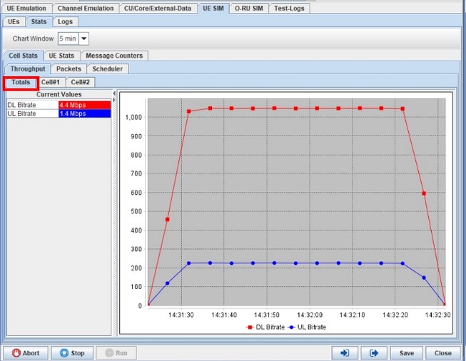
UE-SIM Stats - The Stats panel includes: Cell Stats:
UE Stats:
Message Counters :
UE-SIM - Logs (Simnovator Logs)
The Logs tab covers the logging provided by Simnovator.
Part of the Logs tab configuration is how many log messages are to be stored in the client. Select Max Logs - Options : 1000, 10000, 20000, 50000. There are 4 choices, to help keep memory usage within reason. The text box to the right showing 0 will indicate the current number of messages received and stored by the client. Once the max logs is reached the oldest logs are deleted as new logs are received. If you change the max logs to a smaller value, the old logs will be deleted until the max value is reached. The TAS is always writing all logs to the Test.log.txt file, so no logs will be missed. When the test is running and logs are reported, there are several features to help view the logs.
Across the top:
Auto Scroll - By default this is checked and the GUI will automatically keep the logs scrolled to show the most recently received messages. If you uncheck the box, the scrollbar will keep the currently viewed logs in view, until they are deleted by the max logs logic. UL/DL, Layer, Level, UE ID - Selecting values for these fields will filter the messages in the table. These selectors are populated when you run a test, as the different types of log messages are received by the client. Once they are trained, they will keep all values learned. They should only be empty the first time you open a DU Nodal Test. The filters allow multiple selections, as you select items from the drop-down list, they will be added or removed from the filter respectfully. At the end of the test, the Test-Logs and Logs tab information will be combined into one log.txt or log.zip file in the results website. The end of test file for the UE Logs is the "ue.logs.zip" file, e.g. 24-02-08_17.39.05_RID-33_2.1.0_01252024_RUSim_1Cell.ue.logs.zip. The Simnovator Logs will be prefixed with "log:" "info": "UE Emulation expected to run for 180 seconds"
"state": "RUNNING"
"info": "Started"
"log": "{"data":null,"layer":null,"dir":null,"ueid":0,"message":null,"data":null,"index":0,"timestamp":1685711521089,}"
"
|


O-RU SIM
Stats and KPIs
|
O-RU-SIM (added Totals)
|
Configure Settings - O-RU SIM Stats and KPIs
Configure Settings - Logs
Select the number of log messages in Max Logs to store in client before deleting the oldest messages. When setting to a lower value, all messages over the size will be deleted immediately. Options : 1000, 10000 (default), 20000, 50000 The current number of log messages in client memory is displayed in the box next to Max Logs. Max Logs limits the number of log messages kept in the GUI to reduce memory usage. There are several options. The text box to the right indicates how many log messages are currently in memory. Choose a Max Logs Less than current amount will delete oldest logs until we are at max logs limit. Select Clean to delete all filtered logs from client memory, only keep what is shown. The Clean button will delete all the logs not currently shown in the table because they are filtered out. Set your filter to display what you do care about and click CLEAN to remove all the filtered out logs. This is a one time operation, as new logs come in that do not match the filter, they are still stored, hidden but counted. You need to click clean again to force it again. Enter the search criteria in the input box provided. It will be used to search the logs and return any matches that are found. Enter : UL/DL, Layer, UE ID - Selecting values for these fields will filter the messages in the table. These selectors are populated when you run a test, as the different types of log messages are received by the client. Once they are trained, they will keep all values learned. They should only be empty the first time you open a DU Nodal Test. The filters allow multiple selections, as you select items from the drop-down list, they will be added or removed from the filter respectfully. Select Reset to clear all search criteria. Select Fit Columns for all fields to be fitted to the window. Auto Scroll: By default this is checked and the GUI will automatically keep the logs scrolled to show the most recently received messages. If you uncheck the box, the scrollbar will keep the currently viewed logs in view, until they are deleted by the max logs logic. As you move the scrollbar icon, once you stop the currently viewed rows are marked and maintained in view. If the Max Logs are reached, over time your current selected row might be deleted. The scroll bar will be sliding up and up until your log is deleted.
|


Test-Logs
| Test Logs |
ZIP Threshold (MIB) - If the log.txt file gets above the threshold, the TAS will zip the file. Default = 50 View the Test logs - The Test-Logs tab shows messages in the overall context of the DU Nodal Test.
This includes the state of the test : DU Nodal States
At the end of the test, the Test-Logs and Logs tab information will be combined into one log.txt or log.zip file in the results website. Test-Logs will be prefixed with timestamp, their log level (info:, warning:, error:) or "state:" 2023-06-28 09:37:45-05:state: INIT
2023-06-28 09:37:45-05:state: STARTING
2023-06-28 09:37:45-05:info: Configuring Simnovator DuNodalTest
2023-06-28 09:37:45-05:state: CONFIGURE_SIMNOVATOR
2023-06-28 09:37:47-05:info: Configuring Cells
...
2023-06-28 09:37:47-05:info: UE Emulation expected to run for 180 seconds
2023-06-28 09:37:48-05:state: RUNNING
2023-06-28 09:37:48-05:info: Started
2023-06-28 09:39:48-05:info: Elapsed Time : 1min
2023-06-28 09:40:48-05:info: Elapsed Time : 2min
2023-06-28 09:39:45-05:log: "{"data":null,"layer":null,"dir":null,"ueid":0,"message":null,"data":null,"index":0,"timestamp":1685711521089,}"
|

Technical Specifications
Landslide DU Testing is compliant to specifications:
ORAN Alliance Interfaces 7.2x. F1-C, F1-U, E2, O1 (E2 and O1 are H1/23)
Definitions:
- ORAN – Open RAN
- O-CU - (Centralized Unit) - O-RAN Central Unit – a logical node hosting PDCP, RRC, SDAP and other control functions. This can be considered short-hand for the O-CU-CP and O-CU-UP in an O-RAN system.
- O-DU – (Distributed Unit) - O-RAN Distributed Unit: a logical node hosting RLC/MAC/High-PHY layers based on a lower layer functional split. O-DU in addition hosts an M-Plane instance.
- O-RU – (Radio Unit) - O-RAN Radio Unit: a logical node hosting Low-PHY layer and RF processing based on a lower layer functional split. This is similar to 3GPP’s “TRP” or “RRH” but more specific in including the Low-PHY layer (FFT/iFFT, PRACH extraction). O-RU in addition hosts M-Plane instance.
- C-Plane - Control Plane: refers specifically to real-time control between O-DU and O-RU, and should not be confused with the UE’s control plane.
- S-Plane - Synchronization Plane: Data flow for synchronization and timing information between nodes
- U-Plane - User Plane: refers to IQ sample data transferred between O-DU and O-RU
- NSA - Non-Stand-Alone network mode that supports operation of SgNB attached to MeNB
- SA - Stand-Alone network mode that supports operation of gNB attached to a 5G Core Network
5G Glossary Acronyms, Terms and Specifications in 5G-Glossary