RF Interface
The multiple-Client/UE RF Wi-Fi functionality is built into the Wi-Fi Offload Nodal Test case. This functionality supports the emulation of large numbers of Wi-Fi clients with either an over-the-air or a cabled interface toward an Access Point (AP) and Access Controller SUT. This functionality requires an RF Client-emulation Wi-Fi NIC (Network Interface Card).
Each radio on the PCIe card is a fully functional WiFi capable of at least 3x3 (or 4x4) MIMO. The Card takes the outputs/inputs of the radio signal through a set of 3 (or 4) external SMA connectors. These connections can be attached to antenna for over-the-air testing or directly to cables for cabled testing.
Use the Info tab on the Test Session Window to monitor and "live-view" individual UE States/Information.
| NOTE: When the Antennas report their ON/OFF status to the Info tab, they report it starting from the left and move right through all the Antennas. Once it encounters an Antenna in the off mode, it will stop scanning for Antenna status. For example, if Ant 1 and Ant 3 are turned on but Ant 2 is turned off, the Info tab will display that 1 Antenna is enabled. If Ant 1 is off and Ant 2 and Ant 3 are enabled, the Info tab will display no Antenna information. |
| NOTE: There is a feature for Edge box (E10) where we are using external USB sticks to add extra radios, each external radio (wlan) will allow one subscriber to connect. Landslide will be using “TP-Link N150 Wireless High Gain USB Adapter (TL-WN722N)”.
Steps to follow after connecting usb adaptor to E10: - Reboot TS - Reboot TS (optional) - Ipcfg This above step will arrange the wlan correctly. The external wlan will be detected as "ath9k_htc". See Managing Test Server WiFI. |
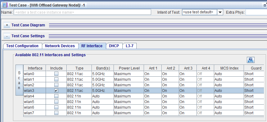
Available 802.11 Interfaces and Settings
The Interface table will display a row for each available Transceiver to be selected for use in the test case. The interfaces are named wlan0, wlan1 etc. Each row is one transceiver on the Wi-Fi card. When a Transceiver is added to a test case, Groups of users/UEs can then be assigned to use the transceiver. All groups of UEs assigned to that transceiver will take on those characteristics defined at the Transceiver level in this table. Other characteristics can be defined at the Group level as described in the UE group Settings.
|
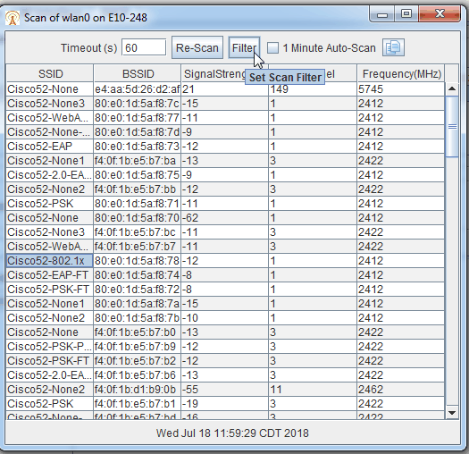
The Scan Button will be enabled when an interface is selected. The on demand scan can only happen when the TS is READY and not running tests, you will get an error back if the TS is unable to scan. When you click the scan button, a request is sent to the TS and when the TS finishes the scan it sends back a report which is displayed in a Scan Results Window. Click for additional details. |
|||||||||||||||||||||||||||||||||||||||||||||||||||||||||||||||||||||||||||||||||||||||||||||||||||||||||||||||||||||||||||
The name of the Wi-Fi interface. (wlan0 through 3) with one card. Add a second card and interface wlan4 through wlan7 become available.
|
|||||||||||||||||||||||||||||||||||||||||||||||||||||||||||||||||||||||||||||||||||||||||||||||||||||||||||||||||||||||||||
| Include | Include the radio in the test case. When included, Radio cannot be used by other test cases at the same time. User may include a radio and then turn off all antennas to ensure other test cases do not use adjacent Radios | ||||||||||||||||||||||||||||||||||||||||||||||||||||||||||||||||||||||||||||||||||||||||||||||||||||||||||||||||||||||||||
| Type | Select which Protocol will be used for that interface, based on NIC type. Supported card types are AC or N. Supported protocols and selections impact what is valid for Antenna, MCS Index and Guard Intervals. All Clients assigned to that interface will attempt to use that protocol. Options: 802.11a, 802.11n, 802.11ac, 802.11g (802.11b is no longer supported) See Matrix for valid options.
|
||||||||||||||||||||||||||||||||||||||||||||||||||||||||||||||||||||||||||||||||||||||||||||||||||||||||||||||||||||||||||
| Band(s) | User selects which band to use. Options : Auto (802.11n only), 2.4 GHZ and 5 GHZ. When Auto band is selected on 802.11n and if both 5G and 2.4G are enabled, client will always connect to 5G radio. When Auto band is selected and if any of the two radios are disabled (5G/2.4G), client will connect to respective enabled radio. | ||||||||||||||||||||||||||||||||||||||||||||||||||||||||||||||||||||||||||||||||||||||||||||||||||||||||||||||||||||||||||
| Power Level | Maximum Power Output (Up to 30 dBm, depends on Chip and Card Vendor - See explanation of Power Settings) or assign attenuation number (how many dBM (decibels relative to one milliwatt) off of the Maximum Power). Options: Maximum, Max - 1 dBm, Max - 2 dBm, Max - 3 dBm, Max - 4 dBm, Max - 5 dBm, Max - 6 dBm, Max - 7 dBm, Max - 9 dBm, Max - 11 dBm, Max - 13 dBm, Max - 15 dBm. Power Setting Ranges:
Power setting ranges are defined by FCC. Power range for the US is from 0 ~ 30 dBm. The following chart shows the TX power setting flow in TX chain:
Power setting dynamic range supported by QCA9880 chip from 5 to 25 dBm. Tx power set to 0 dBm, read back from chip register: 5 dBm ( d_tx_power: 10) Tx power set to 30 dBm, read back from hardware register: 25 dBm (d_tx_power:50) Chip power output range is from 5 ~ 25 dBm.
Power setting actual range from customer PCIe card. The real TX power output from antenna port is up to module/card vendor’s design and implementation. For Compex PCIe card, the external PA (power amplifier) supports: 802.11ac card: 2.4GHz max 19dBm output power & 5GHz max 18dBm output power (per chain) with (-+ 2dB accuracy) 802.11n card: 2.4GHz max 19dBm output power & 5GHz max 19dBm output power (per chain) with (-+ 2dB accuracy) TX power output from Compex PCIe antenna port is in the range from 5~19 dBm. |
||||||||||||||||||||||||||||||||||||||||||||||||||||||||||||||||||||||||||||||||||||||||||||||||||||||||||||||||||||||||||
| Ant 1 | Turns On/Off Antenna. If it is the only antenna on for the transceiver the clients assigned to that transceiver will be transmitting 1x1 only. If 2 antennas are on, transceiver will transmit 2X2 MIMO if supported both by the selected protocol and the AP. If 3 antennas are on, transceiver will transmit 3X3 MIMO if supported both by the selected protocol and the AP. Options: on/off
|
||||||||||||||||||||||||||||||||||||||||||||||||||||||||||||||||||||||||||||||||||||||||||||||||||||||||||||||||||||||||||
| Ant 2 | See Antenna 1 description. Applies to Antenna 2. Options: on/off | ||||||||||||||||||||||||||||||||||||||||||||||||||||||||||||||||||||||||||||||||||||||||||||||||||||||||||||||||||||||||||
| Ant 3 | See Antenna 1 description. Applies to Antenna 3. Options: on/off | ||||||||||||||||||||||||||||||||||||||||||||||||||||||||||||||||||||||||||||||||||||||||||||||||||||||||||||||||||||||||||
| Ant 4 | Turns On/Off Antenna. This Antenna becomes available when MU-MIMO (Wave-2) is enabled (must have specific card insert on the Test Server - Managing Test Server WIFI) Learn more about MU-MIMO (Wave 2). | ||||||||||||||||||||||||||||||||||||||||||||||||||||||||||||||||||||||||||||||||||||||||||||||||||||||||||||||||||||||||||
| MCS Index | The Modulation and Coding Scheme (MCS) Index Values can be used in conjunction with channel width values to allow you to instantly calculate the available data rate of your wireless hardware. See attached chart. Options: Auto, 0 through 23. 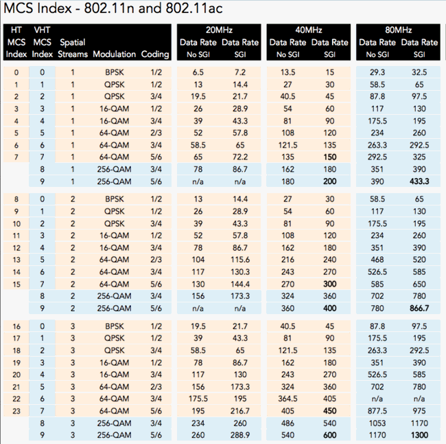
|
||||||||||||||||||||||||||||||||||||||||||||||||||||||||||||||||||||||||||||||||||||||||||||||||||||||||||||||||||||||||||
| Guard interval is used to allow safe time between transmissions. AC card type allows Short interval (400ns) while N card type can use Short (400ns) or Long (800ns) intervals. 802.11a (Protocol A) and 802.11g (Protocol G) do not support Guard interval. When these protocols are used the GUI will set Guard to Auto. Options - Short (400ns) , Long (800ns) , Auto (not supported by protocol type). |
Options
|
Configure WPA Certified Passpoints |
Select to enable Wifi Certified Passpoints. When enabled, a new tab, ANQP Lists (Access Network Query Protocol) is available next to Access Points. Enter up to 16 lists of FQDN ( Fully Qualified Domain names), Realm Names and OUI (Organizationally Unique Identifiers).
|
|
When the test session "Run"s, and the RF interface process starts, it will perform an internal scan to build a table of available Access Points. This table will be used internally until this (WiFi Scan Timeout) specified time period. If the targeted Access Point is not in the internal table, another internal scan will occur to gather the information for the targeted AP. After the WiFi Scan Timeout expires, another internal scan will take place.
|
Access Point
SSIDs
The SSID and BSSID fields are used to identify which AP to connect to the UE Group. The SSID is the name of the logical Wi-Fi network. The BSSID is the MAC address of a Specific AP. If the SSID is entered and the BSSID is left Blank, then the UE group will associate with an AP with the given SSID. If there are multiple APs with the same SSID within range, it will try to associate with the first AP it finds. If it fails to associate with the first AP it will then try to associate with the other APs with the same SSID. If both the SSID and the BSSID are specified, the UE group will only try to associate with that specific AP within an SSID regardless of any other APs in range.
|
Select from 0 up to 16 Access Points. Use the |
|
|
Array of the number of SSIDs selected above. 1 through 16. |
|
|
A text string used as the SSID Name. Tcl Parameter: SsidName_1 (through SsidName_16) |
BSSIDs
This is a two dimensional table indexed by SSID# and Ap#. Use the ![]() Paste Icon to paste BSSIDs from SCAN results.
Paste Icon to paste BSSIDs from SCAN results.
|
Number of Access points selected. Options from 0 to 16.
|
|
|
Include in the list. Tcl Parameter: BssidEn_1_1 Tcl variable name:BssidEn_(SSid#)_(AP#) (1-based indexes) |
|
|
Access Point Name |
|
|
Mac Address of a specific AP. Tcl Parameter: Bssid_1_1 Tcl variable name:Bssid_(SSid#)_(AP#) (1-based indexes) |
ANQP Lists (Only available if Configure WPA Certified Passpoints is enabled)
UE Group Settings
Clients/UEs are configured in groups. Currently, there can be up to 32 groups defined in a single test case. A UE group can have as few as 1 user and as many as are allowed on a single transceiver. The UE group is assigned to transmit out a given Transceiver. Only transceivers selected via the include check box in the Available 802.11 Interfaces and Settings Table are available to be assigned to a UE group in the Assigned Interface drop down. Multiple UE groups can be assigned to the same Transceiver. All UEs within a group share the same authentication type, scan method and transceiver characteristics. However, each UE within a group or across groups have independent state machines for control and data.
To Add a group, select the button. The Group requires Group Name, Number of UEs in Group and the Assigned Interface (Transceiver to be completed).
Note: Be sure not to assign more total UEs/clients to a given receiver than the maximum number of UEs supported by that transceiver.
|
|
Select the number of UE Groups - Up to 32. Tcl Parameter: UeGroupCount |
|
UE Group Number from 1 to 32 |
|
|
UE Group Name from 1 to 32. |
|
|
Total number of UEs - From x to xxx. |
|
Name of the Group - Up to 64 Characters Tcl Parameter: UeGroup1Name (up to UeGroup32Name) |
||
|
Available if Configure WPA Certified Passpoints is enabled in the Options Pane. If enabled, the SSID and BSSID fields are replaced with Excluded SSID and IMSI (Eap-AKA/SIM), MCC, MNC and MSIN. Select to enable ANQP Settings. A dialog box with 3 priorities becomes available. Each contains a combo box selection for Domain, Realm and OUI. The available selections are from the ANQP Lists (Access Network Query Protocol) and include a default of "ANY".
Tcl Parameter: UeGroup1PasspointEn (up to UeGroup32PasspointEn) |
||
|
The number of UEs in a Group.
Tcl Parameter: UeGroup1UeCount (up to UeGroup32UeCount) |
||
|
Select from the available assigned list of Interfaces (enabled via the include tab on the 802.11 interfaces and settings pane) From wlan0 through wlan7 Tcl Parameter: UeGroup1AssignTo (to UeGroup32AssignTo) |
||
|
Specify the Next Hop IP Address to set the MN's next hop to a physical device in the test network. Tcl Parameter: UeGroup1NextHopAddrEn (to UeGroup32NextHopAddrEn) Tcl Parameter: UeGroup1NextHopAddr to (UeGroup32NextHopAddr) |
||
|
The SSID and BSSID fields are used to identify which AP to connect to the UE Group. The SSID is the name of the logical Wi-Fi network. The BSSID is the MAC address of a Specific AP. If the SSID is entered and the BSSID is left Blank, then the UE group will associate with an AP with the given SSID. If there are multiple APs with the same SSID within range, it will try to associate with the first AP it finds. If it fails to associate with the first AP it will then try to associate with the other APs with the same SSID. If both the SSID and the BSSID are specified, the UE group will only try to associate with that specific AP within an SSID regardless of any other APs in range. Tcl Parameter: UeGroup1SsidIndex (to UeGroup32SsidIndex ) From SSID1 up to SSID16. |
||
|
Enable to connect to a hidden SSID. If selected, Step 2 occurs. Sequence of messages for hidden SSID feature: 1. The Hidden SSID will broadcast the Beacon, but does not show the SSID in there. 2. The Client reads this Beacon and then Broadcasts a Probe Request, With SSID set to Broadcast. 3. The Hidden SSID will send back a Probe Request to the client which includes it's SSID. Tcl Parameter: UeGroup1ProbeHiddenSsidEn (to UeGroup32ProbeHiddenSsidEn) |
||
|
Checkbox is enabled if BSSID is something other than "Any". This feature forces the Clients to a specific BSSID. When checked, the group is not eligible for "AP Roaming" or "AP Handoff" for On Demand Command operations. Tcl Parameter: UeGroup1ForceBssidEn (to UeGroup32ForceBssidEn) |
||
|
The SSID and BSSID fields are used to identify which AP to connect to the UE Group. The SSID is the name of the logical Wi-Fi network. The BSSID is the MAC address of a Specific AP. If the SSID is entered and the BSSID is left Blank, then the UE group will associate with an AP with the given SSID. If there are multiple APs with the same SSID within range, it will try to associate with the first AP it finds. If it fails to associate with the first AP it will then try to associate with the other APs with the same SSID. If both the SSID and the BSSID are specified, the UE group will only try to associate with that specific AP within an SSID regardless of any other APs in range. Tcl Parameter: UeGroup1BssidIndex (to UeGroup32BssidIndex) From Any to AP1 through AP16.
|
||
| Excluded SSID |
Enter an SSID or leave blank. Enter up to 64 ASCII characters for SSID value. Only available when Use WPA Certified Passpoint is enabled. Tcl Parameter: UeGroup1ExcludedSsid (to UeGroup32ExcludedSsid) |
|
| IMSI (EAP-AKA/SIM) |
IMSI is made up of three values for MCC, MNC and MSIN. The combined total number of digits must equal 15. MSIN must have 10 digits when MNC has 2, or MSIN must have 9 digits when MNC has 3. GUI and Tcl validation will set an error if the total number is incorrect.
Tcl Parameter: UeGroup1Mcc (to UeGroup32Mcc) Tcl Parameter: UeGroup1Mnc (to UeGroup32Mnc) Tcl Parameter: UeGroup1Msin (to UeGroup32Msin) |
|
| Authentication Type |
There are currently 3 authentication types that can be configured. None - No Authentication, used for OPEN networks WPA2-PSK (AES) - WPA Pre-Shared Keys. Standard Wi-Fi Pass-phrase based Authentication. Requires Pass Phrase to be specified that matches APs pre-configured pass phrase WPS - Wi-Fi Protected Setup (WPS) - Select WPS Mode (Push Button (default) or PIN) 802.1x-EAP -EAP authentication over the 802.1x protocol. Many EAP authentication options are supported including EAP-SIM EAP-AKA EAP-PEAPv0 EAP-PEAP-MSCHAPv2 EAP-TLS EAP-MD5 Note: Each EAP protocol has a set of parameters than need to be defined for correct authentication. These parameters are defined in the EAP section.
Tcl Parameter: UeGroup1AuthType (to UeGroup32AuthType)
|
|
| Link Established Poll Rate (ms) |
The frequency at which to poll the 802.11 link layer for it to become established (associated, authenticated, scan for SSIDs and the EAPOL 4 way exchange) with the AP. Once the 802.11 link layer is successfully established, the OM Link Established Success is set on the WiFi RF tab. The frequency at which to poll the 802.11 link layer for the UE to Roam/Handoff to the Target BSSID. Once the target 802.11 link layer is successfully established, the OM Handoff is set on the WiFi RF Tab.
Default = 1000 Range from 10 to 65535000 Tcl Parameter: UeGroup1AuthStatusPollRate to (UeGroup32AuthStatusPollRate) |
|
| Link Established Timeout (intervals) |
The number of poll intervals at which to give up on the link becoming established and terminate the interface. The OM Link Establish Failures on the Wifi Rf tab will be set. The number of poll intervals at which to give up on the link to roam/handoff to the new BSSID and terminate the interface. The OM Handoff Failures on the WiFi RF tab will be set. Default = 3000 Range from 1 to 65535 Tcl Parameter: UeGroup1AuthStatusTimeout to (UeGroup32AuthStatusTimeout) |
|
| Link Status Poll Rate (ms) |
The frequency at which to poll the link status after it has already become established to see if it is still established (ie. associated) with the AP. If a loss is detected, the Transient Link Disconnect OM will be set on the WiFi RF tab. If the link layer re-establishes before the "Link Status Timeout" has expired, the Transient Link Reconnect OM will be set on the WiFi Rf tab. This value along with the corresponding OMs can be used to detect an unstable 802.11 link layer. I.e A faster poll timer, but a long timeout, and there are a lot of transient link disconnect/reconnects, then there is an unstable RF environment. Default = 1000 Range from 10 to 65535000 Tcl Parameter: UeGroup1EstabStatusPollRate to (UeGroup32EstabStatusPollRate) |
|
| Link Status Timeout (intervals) |
The number of poll intervals at which to determine the link has permanently lost its association with the AP ( and terminate this interface) and it will not re-establish. The OM Actual Link Disconnect on the Wifi Rf tab will be set. Default = 5 Range from 1 to 65535 Tcl Parameter: UeGroup1EstabStatusTimeout to (UeGroup32EstabStatusTimeout) |
|
| Mobility Poll Rate (ms) |
Available in Wifi Offload Gateway Nodal, RF UEs Interface when Test Activity = Command Mode/Sequencer. The frequency at which to poll the 802.11 link layer for it to Roam / Handoff to the specified AP. Once the 802.11 link layer is successfully established, the OM Link Handoff Success is set on the WiFi RF tab. The frequency at which to poll the 802.11 link layer for the UE to Roam/Handoff to the Target BSSID. Once the target 802.11 link layer is successfully established, the OM Handoff is set on the WiFi RF Tab.
Default = 100 Range from 10 to 65535000 Tcl Parameter: UeGroup1MobilityPollRate to (UeGroup32MobilityPollRate) |
|
| Mobility Timeout (intervals) |
Available in Wifi Offload Gateway Nodal, RF UEs Interface when Test Activity = Command Mode/Sequencer. The number of poll intervals at which to give up on the link Roaming / Handing off to the specified AP and terminate the interface. The OM Link Handoff Failures on the Wifi Rf tab will be set. The number of poll intervals at which to give up on the link to roam/handoff to the new BSSID and terminate the interface. The OM Handoff Failures on the WiFi RF tab will be set. Default = 3000 Range from 1 to 65535 Tcl Parameter: UeGroup1MobilityTimeout to (UeGroup32MobilityTimeout) |
|
| Statistics Poll Rate (ms) |
Enter Statistics poll rate in milliseconds. For large capacity tests with many UEs and that are scheduled to run for many hours, we recommend that you set this rate to zero to aid test performance. If using a smaller set of UEs and /or running a test for a shorted amount of time, then set the polling rate to a desired number. Default = 15000 Range from 0 to 65535000 Tcl Parameter: UeGroup1StatisticsPollRate to (UeGroup32StatisticsPollRate) |
|
| Pass Phrase |
The Password to use if WPA-PSK is the selected authentication type. Default = password Range from 8 to 63 characters Tcl Parameter: UeGroup1PassPhrase to (UeGroup32PassPhrase) |
|
| PMK Caching |
This is only valid when a Client roams back to the original AP. The Client will send a Reassociation Request to the AP. If the AP had cached the PMKID, it can skip the 802.1X process and head directly into the 4-wayhandshake. When roaming to an AP for the first time, a full authentication will take place. Default = False Tcl Parameter: UeGroup1PmkCacheEn to (UeGroup32PmkCacheEn) |
|
| 802.11r Over the DS or 802.11w |
Select either 802.11r or 802.11w (mutually exclusive). When this flag is set, Pre-authentication occurs and no EAPOL key exchange takes place as part of Roaming. When 802.11r is enabled, you can select Over the DS (Distribution System) for "802.11r Over the Distribution System FT roaming". If Over the DS is not selected, "802.11r Over-the-Air FT Roaming" is enabled. Tcl Parameter: UeGroup1Dot11rEn to (UeGroup32Dot11rEn) Tcl Parameter: UeGroup1Dot11wEn to (UeGroup32Dot11wEn) Tcl Parameter: UeGroup1Dot11rOverDSEn to (UeGroup32Dot11rOverDSEn) |
|
| EAP Settings |
Enabled when Authentication Type is 802.1x-EAP - EAP settings window will be enabled. |
|
| Opportunistic Key Caching |
The PMK from the first AP is cached in the WLAN controller. The controller will send to the Target AP when the Client tries to reassociate. If flag is not set, then full authentication will take place when roaming to a new AP. If roaming back to an old AP. only a 4 way EAPOL key handshake will occur and full authentication will not take place. Default = True. Tcl Parameter: UeGroup1OpKeyCacheEn to (UeGroup32OpKeyCacheEn) |
|
| Disable SIP VoIP |
Select to disable SIP VoIP traffic for all the UEs in the particular group. Default = False. Tcl Parameter: UeGroup1DisableSipVoIp to (UeGroup32DisableSipVoIp) |
|
| WPS Mode |
WPS Mode becomes available when Authentication Type = WPS ( Wi-Fi Protected Setup) Push Button (Default) or PIN (Enter an 8 digit numerical pin) or use TDF csv file to add a PIN per UE. If Apply Test Data File to Mobile Subscribers is selected, can select to Generate Stub TDF/CSV and select a template to create a CSV file with WPS PIN followed by pin numbers that will be used per UE. This allows for a different PIN per UE. See example CSV file. Tcl Parameter: UeGroup1WpsMode Tcl Parameter: UeGroup1WpsPin |
SCAN Details
| SCAN Details |
Select an Interface and the Scan button is enabled.
A Timeout field is available in both the Scan and Aggregate Scan dialogs. It will default to 60 seconds for Aggregate Scan and 20 Seconds for single port scan. Auto-scan will skip scans that take longer than 10 seconds to complete. It will attempt to perform a scan however, it will skip it if the previous scan is still processing. An optional -timeout N argument has been added to the Tcl API WLAN Scan perform function. This timeout value is provided for when the scan has to process many SSIDs and it takes a very long time. As of Release 17.0, A new Filter Button was added to both Aggregate and regular WLAN scan dialogs. When selected, a new Filter dialog pops up, allowing you to pick up to 5 channels to filter by. The filters are globally remembered while the Client is not shutdown, client shutdown will reset the filters. They are remembered as follows:
On the Scan windows the title bar will display the current filter being applied as seen below (Scan of Wlan0:ch:2, 48 on E10-248. Warning: Do not attempt to perform a FILTERED SCAN on a older Test Server that does not support it as it may recycle the Test Server.
When you click the scan button, a request is sent to the TS and when the TS finishes the scan, it sends back a report which is displayed in a Scan Results Window:
Example with Hidden SSID:
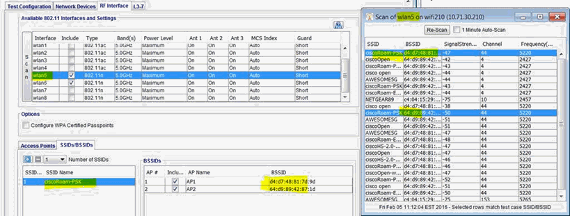
When you scan from within the test case, you also get auto-highlighting of SSIDs/BSSIDs that match something in your test case:
The rows that match ciscoRoam-PSK SSID are auto-selected. On the results menu:
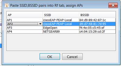
The Results window has sortable columns and data can be copied, either by cell or groups of cells (rows/columns). Can Paste Copied data directly to RF Interface SSIDs/BSSIDs tab: click the Paste button:
You can paste any CSV format from clipboard, it expects rows of SSID, BSSID, may paste from a Spreadsheet
This pops up dialog to assign APs to each SSID/BSSID pair:
Will get enough APs to match the number of SSID/BSSID pairs you have, then click OK it will automatically fill in your test case:
|


