Ap Rf Interface
The basic AP emulation is built into the Wi-Fi Offload Nodal Test case. This functionality is mutually exclusive with RF UEs interface. This functionality will simulate a software AP. Each AP supports up to 200 clients.
Data Traffic Settings for RF AP:
If Data Traffic is not selected:
- whatever is received on the Wifi port is forwarded to the Eth port
-
whatever is received on the Eth port is forwarded to the Wifi port
If Data Traffic is not selected and the “UE to UE Data” button is selected (on the AP settings on the AP RF Interface tab)
-
Whatever is received on the Wifi Port (from UE 1) will be forwarded on to the Wifi Port (to UE 2)
If Data Traffic is selected:
-
Local Network Host should be used.
-
If the DMF Role is Default or Client, the UE on the AP will initiate the Data on the Wifi Port and expect the response on the Wifi Port.
-
If the DMF Role is Server, the UE on the AP will receive the Data from the Wifi Port and respond back on the Wifi Port.
-
The messages from the UE on the AP will have the Src address to be the AP’s interface address and the Destination is the UE’s IP address.
DHCP Settings for RF AP:
- If DHCP Relay Node Emulation in Wifi Offload Test Case is enabled, then the Access point will act as a DHCP Relay Node. Specify the DHCP server in the DHCP Relay Agent Tab. The DHCP Server Address can be remote or Local.
- The DHCP Server Address can be Remote or Local. If the DHCP Server Address is Local, do not select "Process Broadcast DHCP Messages" on the DHCP Server Node Test Case.
- Proprietary Extension Settings may be setup on the DHCP server node, mainly the DNS Server and the Router IP.
| NOTE: TestNodes must not be local loopback (lo) with RF AP Emulation Enabled. If local loopback (lo) is selected in RF AP Node, DHCP Relay Agent Node, and L3-7 Local Node, you will receive error "TestNodes must not be local loopback with RF AP Emulation Enabled". |
Use the Info tab on the Test Session Window to monitor and "live-view" individual UE States/Information.
|
|
|
|
Select SSID in table to view settings |
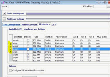
Available 802.11 Interfaces and Settings
The Interface table will display a row for each available Transceiver to be selected for use in the test case. The interfaces are named wlan0, wlan1 etc. Each row is one transceiver on the Wi-Fi card.
|
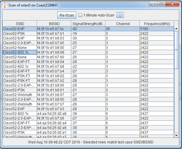
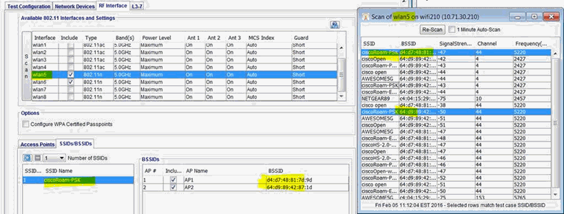
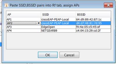
The Scan Button will be enabled when an interface is selected. The on demand scan can only happen when the TS is READY and not running tests, you will get an error back if the TS is unable to scan. When you click the scan button, a request is sent to the TS and when the TS finishes the scan it sends back a report which is displayed in a Scan Results Window. Click for additional details. |
|||||||||||||||||||||||||||||||||||||||||||||||||||||||||||||||||||||||||||||||||||||||||||||||||||||||||||||||||||||||||||||||||||||||||||||||||||||||||||||||||||||||||||||||||||||||||||||||||||||||||||||||||||||||||||||||||||||||||||||||||||||||||||||||||||||||||||||||||||||||
| The name of the Wi-Fi interface. (wlan0 through 3) with one card. Add a second card and interface wlan4 through wlan7 become available. | |||||||||||||||||||||||||||||||||||||||||||||||||||||||||||||||||||||||||||||||||||||||||||||||||||||||||||||||||||||||||||||||||||||||||||||||||||||||||||||||||||||||||||||||||||||||||||||||||||||||||||||||||||||||||||||||||||||||||||||||||||||||||||||||||||||||||||||||||||||||
| Include | Include the radio in the test case. When included, Radio cannot be used by other test cases at the same time. User may include a radio and then turn off all antennas to ensure other test cases do not use adjacent Radios | ||||||||||||||||||||||||||||||||||||||||||||||||||||||||||||||||||||||||||||||||||||||||||||||||||||||||||||||||||||||||||||||||||||||||||||||||||||||||||||||||||||||||||||||||||||||||||||||||||||||||||||||||||||||||||||||||||||||||||||||||||||||||||||||||||||||||||||||||||||||
| Type | Select which Protocol will be used for that interface, based on NIC type. Supported card types are AC, A, G or N. Supported protocols and selections impact what is valid for Antenna, MCS Index and Guard Intervals. All Clients assigned to that interface will attempt to use that protocol. Options: 802.11a, 802.11n, 802.11ac, 802.11g (802.11b is no longer supported) See Matrix for valid options.
|
||||||||||||||||||||||||||||||||||||||||||||||||||||||||||||||||||||||||||||||||||||||||||||||||||||||||||||||||||||||||||||||||||||||||||||||||||||||||||||||||||||||||||||||||||||||||||||||||||||||||||||||||||||||||||||||||||||||||||||||||||||||||||||||||||||||||||||||||||||||
| Band(s) | User selects which band to use. Options : Auto (802.11n only), 2.4 GHZ and 5 GHZ. When Auto band is selected on 802.11n and if both 5G and 2.4G are enabled, client will always connect to 5G radio. When Auto band is selected and if any of the two radios are disabled (5G/2.4G), client will connect to respective enabled radio. | ||||||||||||||||||||||||||||||||||||||||||||||||||||||||||||||||||||||||||||||||||||||||||||||||||||||||||||||||||||||||||||||||||||||||||||||||||||||||||||||||||||||||||||||||||||||||||||||||||||||||||||||||||||||||||||||||||||||||||||||||||||||||||||||||||||||||||||||||||||||
| BW | Select Bandwidth. Options: 20MHz, 40MHz, 80MHz and 160MHz (based on Type). | ||||||||||||||||||||||||||||||||||||||||||||||||||||||||||||||||||||||||||||||||||||||||||||||||||||||||||||||||||||||||||||||||||||||||||||||||||||||||||||||||||||||||||||||||||||||||||||||||||||||||||||||||||||||||||||||||||||||||||||||||||||||||||||||||||||||||||||||||||||||
| Channel | Select the AP Channel from the list. | ||||||||||||||||||||||||||||||||||||||||||||||||||||||||||||||||||||||||||||||||||||||||||||||||||||||||||||||||||||||||||||||||||||||||||||||||||||||||||||||||||||||||||||||||||||||||||||||||||||||||||||||||||||||||||||||||||||||||||||||||||||||||||||||||||||||||||||||||||||||
| Power Level | Maximum Power Output (Up to 30 dBm, depends on Chip and Card Vendor - See explanation of Power Settings) or assign attenuation number (how many dBM (decibels relative to one milliwatt) off of the Maximum Power). Options: Maximum
Power Setting Ranges:
Power setting ranges are defined by FCC. Power range for the US is from 0 ~ 30 dBm. The following chart shows the TX power setting flow in TX chain:
Power setting dynamic range supported by QCA9880 chip from 5 to 25 dBm. Tx power set to 0 dBm, read back from chip register: 5 dBm ( d_tx_power: 10) Tx power set to 30 dBm, read back from hardware register: 25 dBm (d_tx_power:50) Chip power output range is from 5 ~ 25 dBm.
Power setting actual range from customer PCIe card. The real TX power output from antenna port is up to module/card vendor’s design and implementation. For Compex PCIe card, the external PA (power amplifier) supports: 802.11ac card: 2.4GHz max 19dBm output power & 5GHz max 18dBm output power (per chain) with (-+ 2dB accuracy) 802.11n card: 2.4GHz max 19dBm output power & 5GHz max 19dBm output power (per chain) with (-+ 2dB accuracy) TX power output from Compex PCIe antenna port is in the range from 5~19 dBm. |
||||||||||||||||||||||||||||||||||||||||||||||||||||||||||||||||||||||||||||||||||||||||||||||||||||||||||||||||||||||||||||||||||||||||||||||||||||||||||||||||||||||||||||||||||||||||||||||||||||||||||||||||||||||||||||||||||||||||||||||||||||||||||||||||||||||||||||||||||||||
| Ant 1 | Turns On/Off Antenna. If it is the only antenna on for the transceiver the clients assigned to that transceiver will be transmitting 1x1 only. If 2 antennas are on, transceiver will transmit 2X2 MIMO if supported both by the selected protocol and the AP. If 3 antennas are on, transceiver will transmit 3X3 MIMO if supported both by the selected protocol and the AP. Options: on/off | ||||||||||||||||||||||||||||||||||||||||||||||||||||||||||||||||||||||||||||||||||||||||||||||||||||||||||||||||||||||||||||||||||||||||||||||||||||||||||||||||||||||||||||||||||||||||||||||||||||||||||||||||||||||||||||||||||||||||||||||||||||||||||||||||||||||||||||||||||||||
| Ant 2 | See Antenna 1 description. Applies to Antenna 2. Options: on/off | ||||||||||||||||||||||||||||||||||||||||||||||||||||||||||||||||||||||||||||||||||||||||||||||||||||||||||||||||||||||||||||||||||||||||||||||||||||||||||||||||||||||||||||||||||||||||||||||||||||||||||||||||||||||||||||||||||||||||||||||||||||||||||||||||||||||||||||||||||||||
| Ant 3 | See Antenna 1 description. Applies to Antenna 3. Options: on/off | ||||||||||||||||||||||||||||||||||||||||||||||||||||||||||||||||||||||||||||||||||||||||||||||||||||||||||||||||||||||||||||||||||||||||||||||||||||||||||||||||||||||||||||||||||||||||||||||||||||||||||||||||||||||||||||||||||||||||||||||||||||||||||||||||||||||||||||||||||||||
| MCS Index | The Modulation and Coding Scheme (MCS) Index Values can be used in conjunction with channel width values to allow you to instantly calculate the available data rate of your wireless hardware. See attached chart. Options: Auto, 0 through 23. 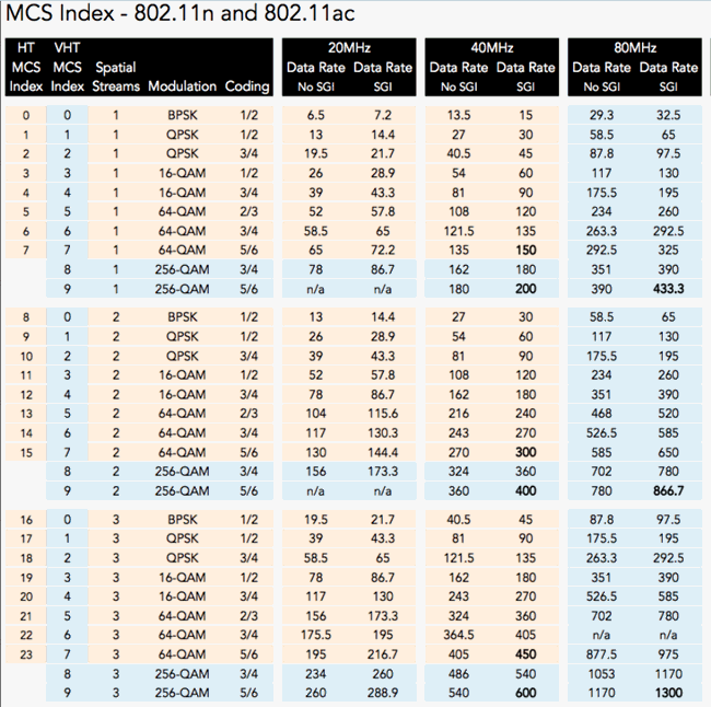
|
||||||||||||||||||||||||||||||||||||||||||||||||||||||||||||||||||||||||||||||||||||||||||||||||||||||||||||||||||||||||||||||||||||||||||||||||||||||||||||||||||||||||||||||||||||||||||||||||||||||||||||||||||||||||||||||||||||||||||||||||||||||||||||||||||||||||||||||||||||||
| Guard interval is used to allow safe time between transmissions. AC card type allows Short interval (400ns) while N card type can use Short (400ns) or Long (800ns) intervals. 802.11a (Protocol A) and 802.11g (Protocol G) do not support Guard interval. When these protocols are used the GUI will set Guard to Auto. Options - Short (400ns) , Long (800ns) , Auto (not supported by protocol type). |
Access Point Settings (One Access Point is supported)
SSIDs
The SSID is the name of the logical Wi-Fi network on the simulated software access point.
|
Max of 1 SSID. Tcl Parameter : SsidCount |
|
|
Array of the number of SSIDs selected above. Only one SSID is supported. |
|
|
A text string used as the SSID Name. Tcl Parameter: SsidName_1 |

