Building an IMS AKA DMF
In order for an MN to participate in IMS services, it must first successfully register with the IMS. During registration, the MN and the P-CSCF negotiate a common security mechanism and then the MN and the IMS authenticate each other using IMS Authentication and Key Agreement (AKA) after secure communications have been established between the MN and the P-CSCF. All security negotiations are transported by SIP and all SIP exchanges except the initial registration attempt are protected with IPSec.
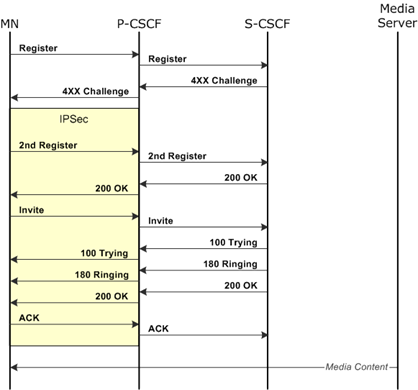 This topic will show you how to construct DMF message sequences that you can use to test a P-CSCF in a nodal configuration. One DMF will generate messages from the MN towards the S-CSCF via the P-CSCF and a second will generate messages from the S-CSCF towards the MN via the P-CSCF. The message flow to the right illustrates the goal of this example: an MN registers with the S-CSCF and accesses content such as streaming video.
The MNs will execute a DMF that consists of three parts:
-
A SIP mainflow that initiates the authentication session, attempts to establish an IPSec connection with the P-CSCF, and controls the overall Data Traffic transaction.
-
A SIP subflow, initiated after the IPSec connection is established, that continues and completes the authentication session.
-
A subflow that represents IMS content delivery using RTP.
Two Network Host test cases will execute DMFs that emulate the S-CSCF and the Media Server:
-
A SIP DMF that responds to messages received from the P-CSCF and participates in the registration process initiated by the MN.
-
A RTP DMF that represents IMS content delivery.
You should become familiar with IMS AKA and with the following topics before attempting to build these DMFs.
MN Message Flow
If possible, start with a non-encrypted message trace between the MN and the P-CSCF and import the SIP messages. Save the DMF derived from the trace and use it as the starting point for both the SIP mainflow and the SIP subflow.
SIP Mainflow — Part 1
The mainflow will only handle one message exchange — the initial register attempt and the challenge response — but it contains almost all of the information required to provision the messages sent in the subflows. The mainflow also specifies when key calculation is performed, when the IPSec tunnel is established, and when each subflow is executed.
The defined message content of the response messages need not match the actual content received, but you must enable message verification for each response message and verify enough bytes to ensure that you are processing the correct message.
-
Open your imported SIP DMF. The first Command control of this DMF will contain the first register request and the challenge response. Delete all other controls and save the DMF under a new name.
-
Review the protocol settings and modify the ports, segment size, and retry settings if necessary.
-
Set Transactions to 1.
-
Click the Security Options button and configure the settings following the IMS AKA guidelines in DMF Security Options. Since a Network Host will be the authenticator, almost any setting is acceptable as long as it is mirrored in the Network Host settings. For this topic, it is assumed that the same keys are used for both AKA and IPSec (Use AKA in IPSec is checked).
-
 Click the Paste Buffer Configuration button and configure two buffers that will be used to form the MN private and public identifiers. The identifier that will be used in the MD5 calculation must be defined in the first buffer. Use an Auto Increment format to produce unique identifiers for every MN. Give each buffer a Name so that the fields can be more easily identified, and set a Size that is large enough to accommodate the largest ID.
TIP: You can make your DMF more portable and more flexible by using buffers to provision network-specific information in the SIP headers.
-
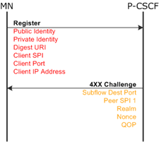 Modify the register request message in step 1 to insert dynamic information as shown in the message flow. Inserted information is shown in red and captured information is shown in gold in the example diagrams.
-
Replace every occurrence of public and private identities with your buffer values by using Paste_privateID and Paste_publicID fields (assuming you renamed the buffer).
-
Use an Insert Digest URI field to replace the existing URI with the value that you defined in Security Options.
-
Use a Source IP Address field to provision the client IP address since it will be different for every MN.
-
-
In the Register request, the client informs the P-CSCF of its security requirements and capabilities with a Security-Client header. The attributes in your header should match the settings in your test configuration. In the example header below, the authentication algorithm (alg) and encryption algorithm (ealg) both match the settings in the Security Options window and on the Data IPSec tab — md5 and 3DES in this example.
Security-Client: ipsec-3gpp; alg=hmac-md5-96; ealg=des-ede3-cbc; spi-c={Insert_Source_SPI_1}; spi-s=12345678; port-c={Insert_Subflow_1_Src_Port}; port-s=1357
Use an Insert Source SPI 1 and an Insert Subflow 1 Src Port to inform the proxy of the SPI and port that the client will use for the IPSec connection. IPSec settings will be addressed later in the topic. -
Information received in the challenge message will be used to calculate the challenge response and to complete the provisioning of the IPSec settings and the SIP subflow.
-
Use an Extract Subflow 1 Dest Port field to capture the port used by the proxy and apply it to the subflow.
-
Capture the SPI that will be used by the proxy with an Extract Peer SPI 1 field to ensure that the correct SPI is applied to the IPSec settings.
-
Use Extract Realm, Extract Nonce, and Extract QOP fields to capture the information from the WWW-Authenticate header that is required to calculate the challenge response. If QOP is not included, "auth" will be assumed.
-
-
At this point, the challenge response can be calculated. Add a Send Event control to the sequence. The event target is <External>, the event applies only to the Client, and the event type is EXECUTE_AKA.
-
Next, the IPSec connection is established. Add another Send Event to the sequence to trigger the connection attempt. The event target is <External>, the event applies only to the Client, and the event type is IPSEC_TUNNEL_1_START.
-
Add a Wait For Event to the sequence and configure it with the same settings as the previous step. This will force the DMF to pause until the IPSec connection is ready for traffic.
-
Save the DMF.
-
The subflows must be added before the mainflow can be completed. Add your imported SIP DMF and add the RTP UDP Subflow from the Basic Library. Check the ports in the RTP subflow and make sure that they will not conflict with the ports used in any of the other DMFs.
SIP Subflow
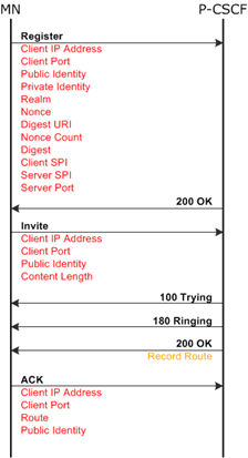 The SIP subflow completes the registration process and establishes the connection with the media server. All of the messages in this subflow will be protected by IPSec. The example diagram shows one example of a SIP trace and the dynamic information exchanged.
|
NOTE: The buffer fields that you defined for the mainflow will be used in this subflow. You can define additional fields in the subflow to capture new information but make sure that you only use fields that have not been defined in the mainflow. |
-
Open the subflow and save it under a different name.
-
Delete all controls that precede the second Register request.
-
Set the Server Port to 0 since you provisioned it with a field in step 8 above.
-
The Client Port must be different than the port used in the mainflow. Modify it if necessary.
-
Review the protocol settings and modify the segment size and retry settings if necessary.
-
Set Transactions to 1.
-
The second Register request includes the client's challenge response. You will need to insert the response using the following fields and also include the same fields that you used in the first request.
-
Insert Realm pastes the realm captured from the challenge.
-
Insert CNonce and Insert Nonce Count paste the values that you defined in Security Options.
-
Insert Digest pastes the hashed challenge response.
-
-
Modify the remaining messages to include the information shown in the diagram. Define a new buffer to capture Record-Route from the final OK and include it in the ACK.
-
Since there will be no response to the ACK message, add a Send Event to the end of the sequence and send a TRANS_COMPLETE that applies to Both to the <Mainflow>.
-
Save the subflow and close it.
SIP Mainflow — Part 2
Now that the subflows have been added, you can add the remaining event controls to complete your mainflow. The last control in the DMF should be the Wait Event associated with the IPSec connection.
-
Wait events can only be followed by other Wait events or Command controls. Add a new Command control to the sequence but do not define any messages.
-
Add a Start Sub control to the sequence and select your SIP subflow.
-
The subflow will send an event back to the mainflow when it is completed. Add a Wait For Event control that listens for TRANS_COMPLETE from the SIP subflow.
-
Repeat steps 1 — 3 and configure the events to start the RTP subflow and wait for it to complete.
-
Save the mainflow.
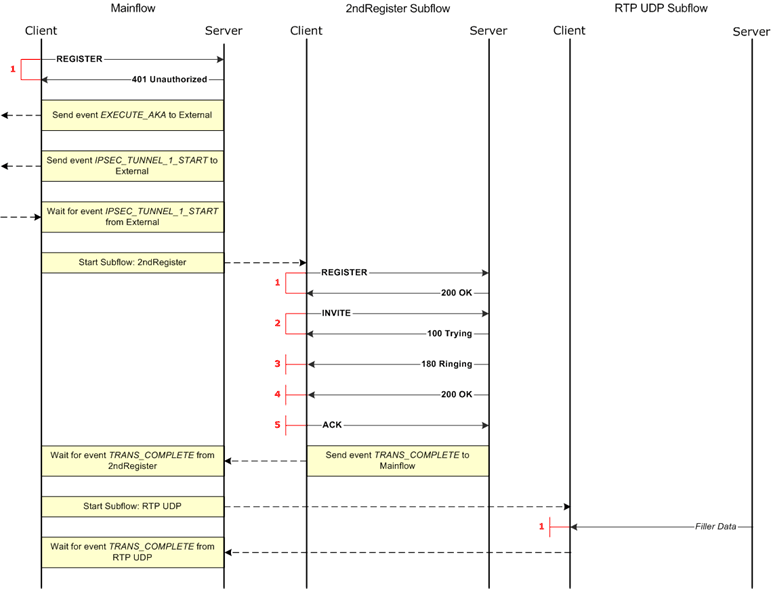
Your MN DMF is complete and should operate similar to the diagram below. Review the message sequences and content of the SIP message flows. Use the Auto-Fill Viewer to check the placement of your paste and insert fields.
Test Case Configuration
Set up two remote Network Hosts in your MN test case: one with the address of the P-CSCF and one with the address of the Network Host that will emulate the Media Server. Click Instances and Assignments... and map the message flows to the hosts. Assign the two SIP message flows to the P-CSCF and the RTP subflow to the Network Host.
Enable Data IPSec and configure the following settings:
-
The information normally negotiated with IKE has been established with AKA and we will be using that information. Select Pre-Provisioned from the IKE drop-down list.
-
Set Authentication Type and Peer Authentication Type to HMAC96-MD5, matching the AKA algorithm.
-
Set Peer Public Key Type and Private Key Type to 3DES, matching the ealg attribute in your SIP security header.
-
Enter values in all of the "key" fields. These values will not be used but the test case requires that the fields have entries.
-
Configure the tunnel settings to select only the traffic generated by the SIP subflow:
-
Protocol Type is UDP.
-
Payload Source Port should match the subflow's Client Port.
-
Enter the IP address of the P-CSCF in Security Gateway Address and Payload Destination ID.
-
Enter a Source SPI and enter some value in Peer SPI. The peer value will be replaced by the value you capture from the challenge message.
-
Set ESP Data Mode to Transport.
-
Clear the Automatically Start Tunnel box since IPSec initiation will be triggered from within the DMF.
-
S-CSCF Message Flow
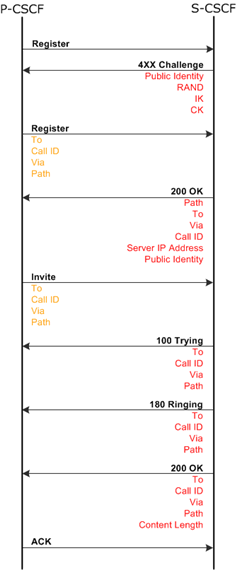 As with the MN flow, the best starting point for the S-CSCF flow is an imported trace. The subscriber profile, which is maintained by the HSS, contains the MN's private identity, the secret key associated with the private identity, and one or more public identities as well as other information required to deliver selected services. The private identity and secret key are used during authentication and are only known to the MN, to the HSS, and to the S-CSCF (when informed by the HSS). Since the test system will emulate the S-CSCF, an HSS is not required — information normally conveyed to the S-CSCF from the HSS is provisioned in the Security Options.
This Network Host will only be responding to messages received from the P-CSCF. It will not be communicating directly with the MNs and therefore it only needs to support one source IP address. Turn on message verification for all of the request messages received to ensure that you are extracting information from the right message.
IPSec may be used between the P-CSCF and the S-CSCF when the proxy is in a foreign network or there may be security gateways between the two nodes. If so, you can support IPSec with the Network Host test case.
-
Add your imported trace to the test case and save the DMF under a new name.
-
This message flow will begin with the first Request message and continue through the SIP session set up. Delete any other controls.
-
In this case, the P-CSCF is the client. Adjust your ports, segment size, and retries accordingly.
-
Configure your first two buffers and the Security Options to mirror the settings in the MN DMF except for Use AKA in IPSec. Any IPSec connection between the P-CSCF and the S-CSCF is independently established and is not part of MN registration.
-
Insert a blank Command control at the top of the message sequence and then insert a Send Event immediately following it. An event cannot be the first control in the sequence and the keying material must be calculated before the host can respond to the first message. Configure the Server to send an EXECUTE_AKA event to <External>.
-
Modify the challenge message and replace the following information with fields:
-
Replace the MN's public identity with the applicable buffer field.
-
Replace the encrypted challenge with an Insert RAND field.
-
Replace the Integrity Key and Cipher Key values with Insert IK and Insert CK fields respectively. The proxy will strip these keys from the response before forwarding it on to the MN. It uses the keys to encrypt, decrypt, and validate subsequent messages exchanged with the MN.
-
-
Modify the remaining messages to capture and insert the information shown in the diagram using a mix of buffer fields and single-purpose fields.
Media Server Message Flow
Configure a second Network Host test case to execute the RTP UDP Subflow DMF. This test case will be communicating with the MNs. Set Number of Source IP Addresses to support the total number of unique IP addresses that will be used by the MNs.
Putting It All Together
Complete your test session by adding Automation Control. The Network Host test cases should be running before the MN test case starts and they should not stop until the MN test case stops.