The SMS Network Test Case
Landslide SMS Network Test Case supports the SMS, SMS-HLR, MAP-C, MAP-D, MAP-E and SGd / S6c / SGs Interfaces.
A high level view of the network architecture that has been targeted is shown below. Three network elements and interfaces will be available in the initial phase of development – namely emulating an SMS-SC, emulating an HLR (with regards to SMS), and emulating an MSC (with regards to SMS).
(SMS-Network (HLR) will take role of HLR, SMS-Ntwk(SC) will take role of SMSC, SMS-Ntwk(MSC) will take role of SMSF/SMS-IWF
MAP operations : (UpdateLocationRequest / PurgeMS / AlertServiceCentre / ReadyForSM / InsertSubscriberData) have been added in the SMS Network Test Case for Registration, Deregistration, Alert SC, Subscription Change in HLR, MT-ForwardSM, MT-ForwardSM-Failure, MO-ForwardSM. MAP call flows will be supported in SMS Network (HLR), SMS Network(MSC) and SMS Network(SC).
SMS Network (HLR) can take the role of HLR, SMS Network (SC) can take the role of SMSC, SMS Network (MSC) will take role of SMSF/SMS-IWF.
Reference : 3GPP TS 29.002: "Mobile Application Part(MAP) specification" Release 16
SMS Network Architecture
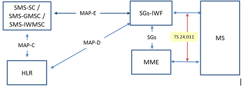
In the above diagram the SGs-IWF is equivalent to an MSC.
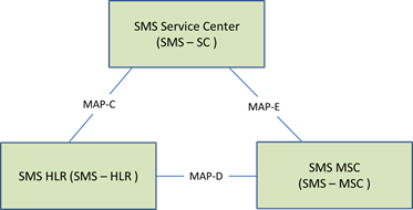
There are no specifications that explicitly define the MAP-C, MAP_D, or MAP-E interfaces. There is a single MAP specification (3GPP 29.002) which defines all the various MAP services. Within this spec there is a section for the Short Message service, defining which map services it uses and between which nodes the services apply.
-
The MAP-E interface carries SMS messages embedded in MAP messages – either Mobile Terminating (MT) from the SMS-SC towards the MN, or Mobile Originating (MO) from the MN towards the SMS-SC.
-
The MAP-C interface is used by the SMS-SC to obtain routing information for an SMS message so that it knows which SGs-IWF to send the SMS message.
-
The MAP-D interface is used by the MSC/VLR to inform the HLR of the whereabouts of the mobile subscriber.
-
The SMS-HLR
-
SGd is a diameter interface that carries SMS messages between an MME and an SMS entity. SGd interface is referenced in 3GPP TS 29.338 (14.1.0).
-
S6c is a diameter interface that carries routing information between an HSS and an SMS-GMSC. When an SMS message is being sent to a mobile subscriber via the SGd interface, the SMS-GMSC sends an S6c routing info request (Send-Routing-Info-for-SM-Request) to the HSS to determine on which MME the destination subscriber is registered. The HSS responds with routing information that the SMS-GMSC uses to send the SMS message towards the correct MME. The HSS determines the routing information to send using information it receives over the S6a interface (when the MME sends an Update Location Request to the HSS). A stand-alone S6c application is NOT provided. In the SMS Network test case, the S6c interface must be enabled along with the SGd interface.
-
 3GPP TS 29.338 (14.1.0) – this defines the Diameter based interfaces specific to SMS when used with SMS in MME architecture. This includes the S6c, SGd, and Gdd interfaces. The Gdd interface is not applicable. 3GPP TS 29.272 (15.6.0) defines the S6a interface.
 -
SGs is the interface between the MSC and MME.
Landslide will support a limited subset of MAP messages – mainly to obtain the routing info from the HLR and to deliver (or receive) SMS messages to (from) the SGs-IWF/MSC. In the MAP specification the reference is to “services” and not messages. While not exactly the same, the term message as used in this document is analogous to a MAP service as defined in 29.002.
The MAP services/messages initially supported by Landslide are:
-
MAP-SEND-ROUTING-INFO-FOR-SM (map-c)
-
MAP-MO-FORWARD-SHORT-MESSAGE (map-e)
-
MAP-MT-FORWARD-SHORT-MESSAGE (map-e)
-
MAP-UPDATE-LOCATION (map-d)
-
MAP-ANY-TIME-MODIFICATION (map-?) (The emulated HLR will receive and respond to MAP-ANYTIMEUPDATE requests).
-
When the MME uses the SGd interface to send an SMS message originated by a mobile subscriber, it sends a Diameter MO-Forward Short Message request (OFR) to an SMS-IWMSC. When an SMS message is being sent to a mobile subscriber via the SGd interface, a SMS-GMSC sends a Diameter MT-Forward Short Message request (TFR) to the MME. SMS messages from a mobile subscriber are sent via the MME towards the SMS Service Center via Diameter OFR messages (Diameter OFA is the associated answer to the OFR). This is referred to as Mobile Originating SMS (SMS-MO). SMS messages in the other direction (towards the mobile subscriber from the SMS network) are contained within Diameter TFR messages (Diameter TFA is the associated answer to the TFR). This is referred to as Mobile Terminating SMS (SMS-MT).
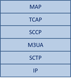
The protocol stack that Landslide supports for MAP is:
Rather than go with the more common node/nodal test case approach a single test case is developed to handle most of the SMS Network testing. In this way a user won’t need to configure multiple test cases in order to do SMS Network testing – it’ll be more or less a one-stop shop.
The SMS Network test case provides the MAP-C, MAP-D, MAP-E, and SMS-HLR interfaces. We’ll be able to emulate or test the following: SMS-SC, HLR, and SGs-IWF (MSC). SMS messages are generated internally by the emulated nodes (SC or MSC).
The concept of “subscriber” is slightly different in the SMS Network test case than most other Landslide test cases. From the perspective of an SMS-SC we don’t “connect” subscribers, all we need to do is send and/or receive SMS messages. We are not emulating subscribers, we are emulating the messages that a subscriber sends/receives.
Mobile Terminating testing (MT) is defined as the SMS-SC sending an SMS message (over the MAP-E interface to an MSC) to a MN. The SMS message can be generated internally by the SMS-SC or (in the future) it can be received over the SMPP interface and forwarded by the SMS-SC. The SMS message is embedded in a MAP message.
Mobile Originating testing (MO) is defined as the SMS-SC receiving an SMS message (from an MSC over the MAP-E interface) for a subscriber. Initially the SMS Network MSC generates the SMS messages internally.
Each emulated node will be driven by its own state machine. There is an SMS-SC Network state machine that drives the SMS-SC functionality. This state machine is responsible for initiating and supporting the various SMS scenarios for an emulated SMS-SC. The SMS-HLR also has its own, separate state machine to control its functionality as does the SMS-MSC.
Existing MAP, SCCP, M3UA, and SCTP drivers/state machines are used by the SMS Network state machines as needed.
SGd Mobile Terminating testing (MT) is defined as the MSC sending an SMS message (over the Diameter SGd interface to an MME) destined for a mobile subscriber. The SMS message is generated internally by the MSC and is embedded in a Diameter TFR message.
SGd Mobile Originating testing (MO) is defined as the MSC receiving an SMS message (from an MME over the SGd interface) that would be forwarded to an SMS Service Center for delivery. The SMS message is contained within a Diameter OFR message but will terminate within the LS emulated MSC (i.e. the SMS message is not forwarded to an SMS-SC).
As related to an MSC, the user can configure SMS-MT, SMS-MO, or both types of testing within the SMS Network test case.
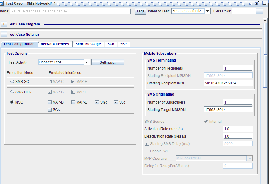
Test Configurations
Each emulated node provides two MAP interface options. The SMS-SC provides a MAP-C and a MAP-E interface, the SMS-HLR provides SMS-HLR, MAP-C and MAP-D interfaces, and the SMS-MSC provides MAP-D, MAP-E, and SGd / S6c /SGs Interfaces. The test case can be configured to support one or both of the interfaces for the emulated node.
Only one SUT of each type (HLR, MSC, SC) will be supported.
SMS-SC
The SMS-SC can be configured to send SMS MT messages to an MSC, receive SMS MO messages from an MSC, and initiate MAP Send Routing Info messages towards the HLR – or any combination thereof.
MAP services supported:
-
MAP-SEND-ROUTING-INFO-FOR-SM (map-c)
-
MAP-MO-FORWARD-SHORT-MESSAGE (map-e)
-
MAP-MT-FORWARD-SHORT-MESSAGE (map-e)
SMS-SC MAP-E enabled
The test can be configured for Mobile Terminating functions, Mobile Originating functions, or both simultaneously.
Mobile Terminating
Number of Recipients (SMS Terminating pane) defines the number of target subscribers to which an SMS message will be sent (from the emulated SC to the MSC). If MAP-C is checked a MAP-SEND-ROUTING-INFO-FOR-SM request is sent to the HLR before the MAP-MT_FOWARD-SHORT-MESSAGE is sent to the MSC. When the response to the send routing info is received, the SC will copy the IMSI from the response and use it in the outgoing MT message. The rate at which the MAP operations are performed (per subscriber) is defined in the Message Interval on the Short Message Tab. If the number of SMS messages is limited (by Message Cycle on the SMS tab) then all messages will stop.
If MAP-C is not selected the SC does not send MAP-SEND-ROUTING-INFO-FOR-SM requests to an HLR. Instead it immediately begins the MT operations.
If Number of Recipients is 0 then the test is setup to only receive MO messages from an MSC.
MT sending is independent of reception of MO messages.
Mobile Originating
Number of Subscribers (SMS Originating pane) defines the number of subscribers for which the SMS-SC can receive MO messages. When an MO request is received by the emulated SC, it will check the MSISDN within the message to make sure that the message is destined for a subscriber that is recognized by this SC. If the MSISDN is not recognized the SC will respond with an error, otherwise it will respond positively. There is no other validation of the SMS.
SMS-SC MAP-C enabled
As noted above when the MAP-C interface is enabled the emulated SC will send MAP Send Routing Info request to the HLR.
The test can be configured for MAP-C only in which the only activity is the SC generating the Send Routing Info request at the rate (per subscriber) specified by Request Routing Info Rate on the MAP-C tab. These messages will continued to be sent until the test is stopped.
When MAP-C is enabled data must be entered in the SMS Terminating area of the Test Configuration tab. That information is used for both MAP-C and MAP-E operations.
SMS-HLR
The SMS-HLR can be configured to support both MAP-C (from the SMS-SC) and MAP-D (from the MSC/VLR) and SMS-HLR simultaneously or individually.
MAP services supported:
-
MAP-SEND_ROUTING-INFO-FOR-SM (map-c)
-
MAP-UPDATE-LOCATION (map-d)
-
MAP-ANY-TIME-MODIFICATION (map-x?)
The HLR simply responds to request received, it does not autonomously generate any MAP requests. The data in the SMS Terminating pane on the Test Configuration tab defines the number of subscribers and their associated identities that are recognized/supported by the HLR. When a MAP request is received the HLR will validate that it recognizes the subscriber identified in the request and if so will respond positively. If the HLR does not recognize the subscriber it will respond with an error.
Note that the HLR does not “save” information from one interface to be used on the other. For example the HLR does not save the MSC address from the Update Location request to send to the SC in response to a Send Routing Info request.
SMS-MSC
The SMS-MSC can be configured to support both MAP-D (from the HLR), MAP-E (from the SMS-SC) simultaneously or individually and SGd interface that carries SMS messages between an MME and an SMS entity.
MAP services supported:
-
MAP-UPDATE-LOCATION (map-d)
-
MAP-MO-FORWARD-SHORT-MESSAGE (map-e)
-
MAP-MT-FORWARD-SHORT-MESSAGE (map-e)
SMS-MSC MAP-D enabled
If MAP-D is enabled the MSC will send a single MAP-UPDATE-LOCATION request for each defined subscriber (Number of Recipients). This is done regardless of the configuration of the MAP-E interface. (Note that the MSC uses the same information from the SMS Terminating pane for both the MAP-D and MAP-E interfaces). After the Update Location is sent there is no other activity on the MAP-D interface for the subscriber.
SMS-MSC MAP-E enabled
The test can be configured for Mobile Terminating functions, Mobile Originating functions, or both simultaneously.
Mobile Terminating
Number of Recipients (SMS Terminating pane) defines the number of target subscribers for which an MT SMS message can be received (from the SC). When an MT message is received the MSC will validate that it recognizes the identity of the target of the message. If the MSC recognizes the identity it will respond positively. If the MSC does not recognize the identity it will respond with an error.
If Number of Recipients is 0 then the test is setup to only for MO operations.
Mobile Originating
Number of Subscribers (SMS Originating pane) defines the number of target subscribers which to send an MO SMS message to the SC. The rate at which the MO messages are sent, per subscriber, is defined in the Message Interval on the Short Message Tab. If the number of SMS messages is limited (by Message Cycle on the SMS tab) then MO messages will stop.
MO sending is independent of reception of MT messages and is independent of MAP-C operations, if any are configured.
SMS-MSC SGd enabled
The concept of “subscriber” is slightly different in the SMS Network test case than most other Landslide test cases. From the perspective of SGd we don’t “connect” subscribers, all we need to do is send and/or receive Diameter SMS messages. We are not emulating subscribers, we are emulating the messages that a subscriber sends/receives.
SGd Mobile Terminating testing (MT) is defined as the MSC sending an SMS message (over the Diameter SGd interface to an MME) destined for a mobile subscriber. The SMS message is generated internally by the MSC and is embedded in a Diameter TFR message.
Using the SMS Terminating pane on the Test Configuration tab the SGd MSC can be configured to send SMS MT messages (Diameter TFR).
-
Number of Recipients (SMS Terminating pane) defines the number of target subscribers to which an SMS message will be sent (from the emulated MSC to the MME). If the Number of Recipients field is non-zero then the Short Message tab will appear. The Short Message Tab is where the SMS information is configured.
-
Starting Recipient IMSI helps define the target mobile subscriber (the destination of the SMS message generated by the emulated MSC).
-
Since LS sends a Diameter message and waits for an answer message for each of the Number of Recipients, a “session” is created for each.
-
If Number of Recipients is 0 then the test is setup to only receive MO messages from an MME. In this configuration, the Short Message tab does not appear.
-
MT sending is independent of reception of MO messages.
SGd Mobile Originating testing (MO) is defined as the MSC receiving an SMS message (from an MME over the SGd interface) that would be forwarded to an SMS Service Center for delivery. The SMS message is contained within a Diameter OFR message but will terminate within the LS emulated MSC (i.e. the SMS message is not forwarded to an SMS-SC).
Using the SMS Originating pane on the Test Configuration tab the SGd MSC can be configured to receive SMS MO messages (Diameter OFR) from an MME.
-
Number of subscribers (SMS Originating pane) defines the number of subscribers for which the SGd MSC can receive MO messages (Diameter OFR). When an MO request is received by the emulated MSC, it MAY check the MSISDN and Service Center Address contained within the OFR message to make sure that the message is destined for a subscriber that is recognized by this MSC. If the MSISDN or Service Center is not recognized the MSC will respond with an error, otherwise it will respond positively. There is no other validation of the SMS. The range of recognized subscribers is defined by Starting Target MSISDN and Number of Subscribers.
-
The SGd tab provides the ability to activate/de-activate the validation of the MSISDN and/or Service Center address.
-
Since LS simply receives a Diameter message and responds to it, there is no concept of a “session” for each subscriber. There is no waiting for a response in this scenario. All signaling can take place over a single “session”.
-
Note: this will have to change in the future if we add the ability for the MSC to forward the received SMS to an SMS service center.
-
MO reception is independent of sending of MT messages.
A new SUT type is defined for SGd on the Network Devices tab. It is used to configure the MME SUT to which the emulated MSC will exchange Diameter SMS messages. It also adds new fields for the MSC Node (active only when SGd is selected). Up to 10 MME SUT devices can be configured. Each SUT requires its own IP address, Host, Realm, and MSISDN. All SUTs will communicate with the single SGd MSC Node (1 is the only allowable value for the “# of Nodes” box).
SGs is defined as the MSC receiving message (from an MME over the SGs interface) that would be forwarded to an SMS Service Center for delivery.
|
NOTES:
|
As related to an MSC, the user can configure SMS-MT, SMS-MO, or both types of testing within the SMS Network test case.
Measurements
Test Summary – Sessions Established / Pending
The SMS Network test cases do not form a “connection” between a subscriber and a device like many other Landslide test cases. For example, there is no subscriber attach or PDP context activation, or anything that resembles that in the SMS network test case. We simple send and receive MAP messages. The “connection” is an SCTP/M3UA connection between nodes (and SMS-SC and an HLR for example) and that single connection carries all MAP messages related to all subscribers.
Because there is no real connection between a node and a subscriber the Test Summary tab only contains a few items as shown here:
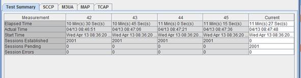
The Sessions Established/Pending counts are somewhat unusual due to the nature of the test. Test scenarios, like the HLR, in which the node simply responds to received messages, only have a count of 1 – regardless of the number of subscribers being supported. When an emulated HLR is started it simply waits for messages to arrive, there is nothing that needs to be done to get the subscriber ready to receive messages. As such the HLR test case goes into a Running State as soon as the SCTP/M3UA connection is established.
Test scenarios in which a MAP message is sent and a response waited for do have the usual sessions established/pending counts. For example, an SC test case with MT operations configured will have a Sessions Established/Pending count equal to the number of recipients configured. The test case goes into the Running State once the first MAP message has been sent for all subscribers.
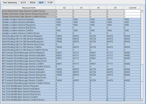
MAP counters
For the MAP message information new rows have been added to the existing MAP tab. These new rows basically indicate the number of MAP requests sent, received, and responded to for each type. The “Request” row is the number of messages of that type sent. The “Indication” row is the number of messages of that type received. The “Confirm” row is the number of successful responses received for the message type, “Confirm Errors” is the number of failures received. The “Response” row is the number of successful responses sent for the message type, “Response Errors” is the number of error responses sent.
For example, an emulated MSC with MAP-D configured you would see counts in the following rows: Update Location Service Request and Update Location Service Confirm (assuming no errors). An emulated HLR for the same test would show counts in the Update Location Service Indication and Update Location Service Response rows.
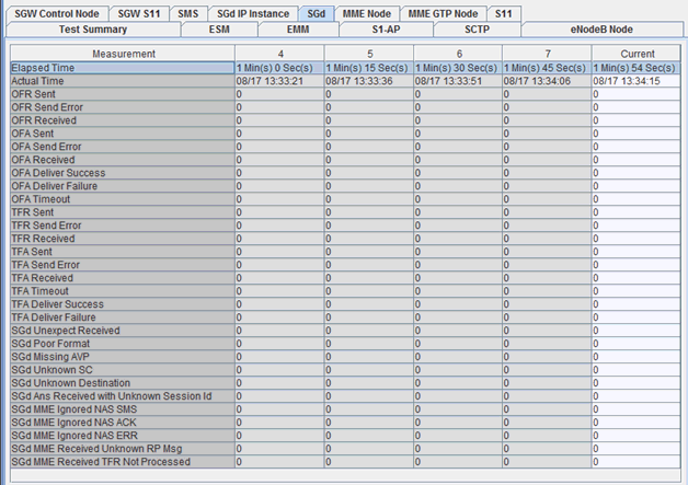
SGd Measurements – common to both MME Node and SMS Network
A new measurements tab (SGd) has been added to both the SMS Network Test case and the MME Node test case (when SGd is enabled):
These new measurements basically indicate the number of Diameter SMS requests sent, received, and responded to for each type.
S6c Measurements are available when S6c Interface is enabled.
SGS Sessions Measurements are available when SGs Interface is enabled.
|
Reference Documents:
|